This thread has been locked.

If you have a related question, please click the "Ask a related question" button in the top right corner. The newly created question will be automatically linked to this question.

TPS65094: how does push-button circuit connect without EC

Part Number: TPS65094
Other Parts Discussed in Thread: TPS51285B, SN74LVC1G04, SN74LVC1G14,

Dear Sir,

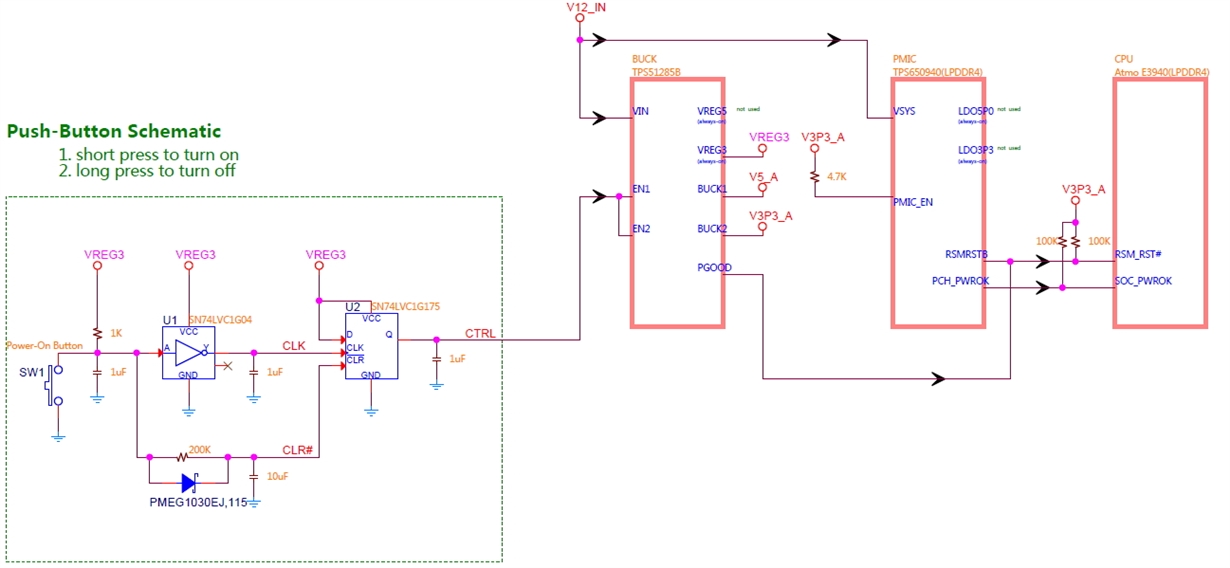
    We are now using TPS650940 as PMIC and TPS51285B as BUCK for Intel APL-I and without EC.

    The BUCK have 2 always-on rails, VREG3 and VREG5 and we use VREG3 only.

    The PMIC  have 2 always-on rails, LDO5P0 and LDO3P3, not used.

    The Power of Push-Button circuit is VREG3 and the output of Push-Button circuit is 'CTRL'.

    Should we connect 'CTRL' to enable pin of BUCK or enable pin of PMIC?

    The attach file is our block circuit.Thanks!

3125.SCHEMATIC1 _ PAGE1.pdf


  • Hello,

    I reviewed the block diagram and the concept match closely to the Push-button application note: 

    One note that I have is that the SN74LVC1G04 likely needs to change to SN74LVC1G14 which is Schmitt triggered and was updated in the original app note.

    I do not see any issue with connecting CTRL to TPS51285B enable. As long as the TPS51285B is powered up before our PMIC_EN goes high, that should allow PMIC to have proper start-up. One test that will be necessary is confirming that the 5V is available when PMIC_EN goes high. It may be desirable to have an RC+diode on the PMIC_EN pin from V3P3_A with the diode connected to CTRL. The RC would delay the PMIC_EN to ensure that the V3P3_A and V5_A are powered up before TPS65094 starts powering up. The diode would ensure PMIC_EN goes low as soon as the CTRL pin goes low. 

    One last point is that you may prefer the TPS650945 instead of TPS650940; it has BUCK3/4/5 in force PWM which improves their performance and stability.

  • Thank you Kevin!