This thread has been locked.

If you have a related question, please click the "Ask a related question" button in the top right corner. The newly created question will be automatically linked to this question.

LM5122: The Application Question

Part Number: LM5122
Other Parts Discussed in Thread: LM3409

Hello support team,

There and any advice on discharge resistor for MOSFET gate to source rules.
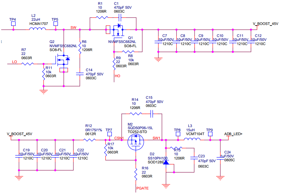
1. In LM5122 Sync Boost topology for wheel N-FET, the R8 / R11 are necessary add?  
2. In LM3409 non-Sync Buck topology for switch P-FET, the R17 is necessay add? 
There are any side-effect or anything benefits? Thanks!

  • Hello,

    It is not necessary to use R11 for the 5122 circuit. The 5122 has an integrated gate driver that will discharge the FET as needed. 

    Your placement of R8 is incorrect and also unnecessary. You would want to tie the resistor from the gate of Q1 to the source. The current configuration would have current flow through the body diode and the device would not turn on.

    The benefit of adding the resistor is that the gate of the FETs will be at a stable state and not float about. Additionally, you have another path to ground that current can go through when discharging the FET.

    The downside of this is that since you have an extra resistive element, you have lowered your efficiency through conduction losses. 

    You will see that it is not entirely necessary to use R17 as well for the LM3409 circuit. The reasoning is the same as above.

    If you would like to see if there is any performance difference, I would recommend putting the footprints of the parts on the PCB, but leaving them open if you do not wish to utilize the pull-up and pull-down resistors (R8, R11, R17), and populating them as desired.

    Thanks,

    Richard