This thread has been locked.

If you have a related question, please click the "Ask a related question" button in the top right corner. The newly created question will be automatically linked to this question.

BQ76PL455A-Q1: TI BD76PL455A-Q1 Reference Design

Part Number: BQ76PL455A-Q1
Other Parts Discussed in Thread: BQ76PL455A, , EMB1499Q, EMB1428Q, EM1402EVM

Hi,

I am using the EM1402 Evaluation Module (TI BD76PL455A-Q1 Reference Design).

A few days ago, the BMS system had 3 cells with voltages readings around 0.006 to 0.6 volts. Now there are 6 cells reading the same. When I read take the cells out of the BMS chain and read the voltages with a meter, the individual cells are reading 2.2 volts as expected.

These cells are causing under voltage  alarms. Once when I forced a balance on the cells, the voltage readings appeared to become correct. The next day the reading were again low. but using a meter the individual cells readings were expected.

Just reaching out to see what may cause such low readings from the chip/board when the meter tells me the correct voltage. Can this be a hardware issue, is it a setup (parameter) issue leading to a timing problem causing incorrect values? Although little change has been done with the setup parameters. 

Any insight is appreciated.

Malcolm

  • Hi Malcolm,

    " Once when I forced a balance on the cells, the voltage readings appeared to become correct"

    Are you measuring with balance ON or after turning on/off?

    Can you do this for me?

    1. Show me the cell measurements of each cell.

    2. Go to PL455A cell balancing register and provide me the register value.

    thanks

    Roger


  • Hi Roger.

    I am out of the office today and will get those measurements for you when I am back.

    As for.your other question. The voltage values remained after balancing.

    Malcolm

  • Hi Roger.

    I am following the sample source code provided by ti but with the #diacharge added in.

    Malcolm

  • Hi Roger,

    For the software block diagram:

    1) Read the voltages of the cells and temperature 

    2) Determine the maxCell and MinCell voltage

    3) Call EMB_Start(0, maxCell, discharger) (This uses calls to register 121)

    4) Delay 1 to 10 seconds

    5)Delay 3 seconds

    6) Repeat back to step 1)

    Is this the recommended approach? Do you have other examples?

    Thanks,

    Malcolm

  • Hi Roger,

    Here are the answers to your questions:

    1) Cell values:

    1) 2.234

    2)2.136

    3) 2.287

    4) 2.258

    6) 2.2189

    7) 2.21134

    8) 2.231

    9) 2.331

    10) 2.134

    11) 2.2089

    12) 0.0061

    13)0.0060

    14)  0,067

    15) 2.214

    16) 2.215

    *Note - In previous measurements the voltages measured for 12, 13, 14 were ok, but cells  4, 5, 6, 7, 8 were in the 0.006 range. So these low voltages appear to move around.

    2) Register values for:

    register 13 was 0x10

    register 14 0x18

    Any advice is appreciated.

    Malcolm

  • Hi Malcolm,

    Thank you for the information. Here are a few recommendations on what to try in order to debug this issue:

    • I would like to figure out first if this is a board level issue or not. You mentioned you read the voltages directly on the cells and they read 2.2V as expected. I recommend measuring on the board as close as possible to the VSENSEx pins of the bq76PL455A device to know the voltage that the devices is actually seeing. Please try this right at power up, before starting the software, and measure both at the cells and directly on the VSENSE pins of bq76PL455A. If there is something happening at board level, you would see the 0.6V on the bq75PL455A pin and that would be why the device reports 0.6V. If you see the 2.2V all the way to the VC pin, then we can start seeing more into the device itself or the software. 
    • At what point in time do you measure the 0.6V on the cells? (e.g. before running the software, when balancing, after balancing stopped)?
    • Did you read registers 0x13 and 0x14 (hexadecimal)? or 13 and 14 (decimal)? Please let me know the values for 0x13, 0x14 as well as 0x15
    • You mentioned you added the "discharge" case to your software. Have you tried running the code without this modification and see if the issue is still present?

    Best regards,

    Leslie

  • Hi Leslie

    Thanks for getting back to me.

    I will get the measurements you asked for and send them to you. I will be busy for much of the day Friday, I find it odd the that low voltage values seem to move around.each time the device is started.

    The values that I mentioned are decimal for the registers and the contents that I reads I provided in hex.

    Thanks for your help

    Malcolm

  • Hi Malcolm,

    Thank you.

    Leslie

  • Hi Leslie

    I did take some measurements. To make a long story short, when I used the scope to take a measurement from a specific cell it measured as a negative voltage. I thought this was odd.The volt meter gave a 2.2V reading. I replaced that cell and all measurements have been correct since.

    Would you know why this might happen? Or better still how this can be detected as a problem cell?

    I am still not able to get the balance to work. I have one cell at 2.1 volts all others are at 2.2 to 2.3. The algorithm I am using detects this as the lowest voltage. I am using the sample codes EMB_Start and EMB_Stop.I appear to get signals to U16 (SN74AHC595QPWRQ1).  I also tried with the GUI provide by TI, but I did seem to balance the cell either.

    If you have any advice, that would be appreciated.

    Thanks for all your help.

    Malcolm

  • Hi Malcolm,

    That is odd... what value do you measure on that cell when you measure it by itself out of the system with the oscilloscope and with the DMM? The only thing I can think of is if you have several instruments connected and you hooked up the oscilloscope to a higher cell (for example to measure voltage on cell 6), you would need to use a differential probe since regular probes are normally referenced to the oscilloscope's ground.

    Regarding your balancing routine, we don't have a GUI that is able to control the EMB devices (EMB1499Q and EMB1428Q). You can only use the BQ76PL455A-Q1 GUI to monitor the cell voltages, but not to do active balancing on the EM1402 EVM (the balancing function in the GUI is to do passive balancing with the BQ76PL455A-Q1, but the EM1402 EVM is only designed for active cell balancing).

    Can you please give more details on what is it that is not working? What part of the code? 

    Regards,

    Leslie

  • Hi Leslie

    Thanks. I will have to review the measurement as I understand the ground needs.

    Thanks for the update about the GUI. Yes.. I can monitor, but that explains why I wasn't able to do a balance. I was always referencing that GUI to  compare  with my values.

    The code that I am using is from the EM1402EVM Example Code 0.1.

    What my code is doing is determining the lowest voltage cell. And then calls:

       if(cellToBalance) // Only balance if celToBalance is not set to 0

       {
        EMB_Start(1, cellToBalance, cellBalanceDir);
        delayms(1000);
        EMB_Stop(1, cellToBalance);
        delayms(3000);
       }

    After about 20 minutes of calling his look there is no change in the displayed volatge.

    I looked at the bit banged SPI signals, which appeared to be ok.

    Is this the correct procedure/function to perform active cell balancing?

    Is     EMB_Vset(0, 2) important for the balancing function?

    Thanks,

    Malcolm

  • Hi Malcolm,

    EMB_Vset() function takes care of setting the balancing current, so it is needed in your routine if you are using the EM1402 board. "Vset" is a pin on the EMB1499Q device. The user sets a voltage on this pin that adjusts the balancing current. You can read more about VSET functionality on the EMB1499Q datasheet: http://www.ti.com/lit/ds/symlink/emb1499q.pdf

    You can look at the EMB_Vset() function and its parameters in the emb1428.c file. 1st parameter is bq76PL455a device address, and 2nd parameter is the balancing current. This routine will then calculate what voltage you must have on Vset to produce the desired balancing current, then select the DAC device (chip select) through the EMB_SetCS() function and then send SPI command to the DAC to set the needed voltage. The DAC output is connected to VSET pin on EMB1499Q.

    Also make sure that you are initializing the EM1428Interface at the beginning before calling EMB_Vset() or the start and stop balancing functions.

    Regards,

    Leslie

  • Hi Leslie,

    There is no voltage on Vset of the EMB14990Q device. That must be why I don't see a voltage change during balance.

     I am assuming I should see the same voltage on pin 1 (DAC_OUT) of U17 on DAC081S101CIM.

    To test, I put my code in a loop caking EMB_Vset(). I started to go through the board to see what was happening but did not uncover anything yet. I did notice on U16 (SN74AHC595QPWRQ1) that all of the chip select output  pins 1, 2 3, and 15 were all toggling.not just the CS_DAC.

    Malcolm

  • Hi Leslie

    I did get the DAC_OUT working. It appears that setting the EMB1428_RST low configured the device to output a voltage.

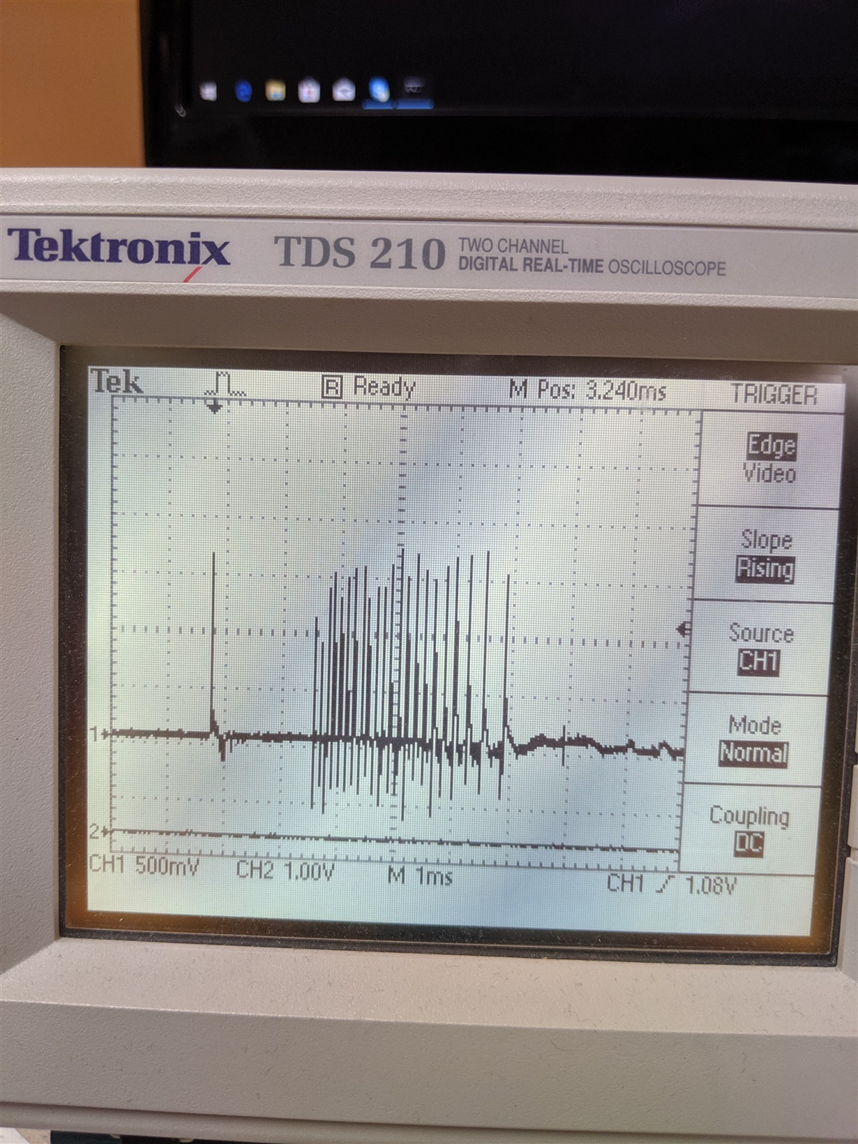
    I still didn't see any change in the voltage of the cell. However, the EMB1499Q EN pin is only high for 10 very quick bursts for about 10ms. Is the EMB1499Q EN pin controller by the enable top, bottom and middle. I am trying to see why the EN is not on solid high and for longer period than 10ms.

    Malcolm

  • Hi Leslie

    Still struggling to see any sign of a change in battery voltage in balance mode.

    I have attached what I see on the output of the EN pin on the EMB1499. 

    Is this the expected output?

    Malcolm

  • Hi Malcolm,

    The EN signal should be high for EMB1499 to begin charging or discharging. This pin should be 5V CMOS output levels. In the scope plot you showed, the signal is very low, about 1.5V peak, which indicates that you are are seeing might be just noise. If it was the actual EN signal, it would be 0V or 5V. 

    Here are a few tips to debug this issue further:

    • Run your code manually stepping into the charge/discharge sequence
    • At the same time, probe the SPI interface to make sure the correct command is getting to the EMB1428 (nCS, CLK, SDI, SDO, FAULT_INT). See "Command Decoding section on page 17 of EMB1428 datasheet to review valid commands: http://www.ti.com/lit/ds/symlink/emb1428q.pdf 

    Best regards,

    Leslie

  • (the 3rd bullet in my previous answer got deleted for some reason. See the rest of my answer below).

    • If SPI command from the MCU to the EMB1428 is correct, then move to probe the signals between EMB1428 and EMB1499 (EN, DIR, DIR_RT, DONE, FAULT[2-0]). See "Normal Control Sequencing" on page 18 of the datasheet for description of what to expect on these pins.

    In summary:

    • EN pin is an output from EMB1428 to indicate to EMB1499 device when to start or stop balancing (start with EN is high and stop when EN is low).
    • DIR pin is an output from EMB1428 too, and it indicates to EMB1499 whether to charge or discharge the selected cell when balancing.
    • DIR_RT is an output from EMB1499 going into EMB1428 and it should be the complement of DIR signal (see timing for this in the datasheet).
    • DONE is an output from EMB1499 to indicate to EMB1428 when the charge/discharge cycle is done (high when the current charge/discharge cycle is done, and low when it is in progress).
    • FAULT[2-0] is an output from EMB1499 to indicate to EMB1428 that a fault occurred. See "Fault Detection and Fault Codes" on page 13 of the EMB1499 datasheet for description of each fault code.

    Best regards,

    Leslie

  • Hi Leslie,

    I did look further into the SPI. I changed the code to use J2. I was able to get clocks at 1MHz.while prior to this the clocks were slower,

    After changing and verifying the signals there may be a current draw on the board that needs to be looked into.

    Now when the balance cycle starts, the green LED close to the bq76pl455a goes off and the second LED that normally goes on when balance is started just lights dimly.Does that I mean I have a high current draw??

    Looking into this I am not sure if this is a problem is related the 12V power supply not supply sufficient current or if I should use 5V on J3 rather then 3.3 which I am using now.

    Any suggestion?

    Malcolm

  • Hi Leslie

    Just confirming you haver received my responses.

    Thanks,

    MAlcolm

  • Hi Malcolm,

    Can you please tell me the LED number in the schematic to be able to find it. Regarding your question about J3, are you refering to the FTDI connector?

    Regards,

    Leslie