This thread has been locked.

If you have a related question, please click the "Ask a related question" button in the top right corner. The newly created question will be automatically linked to this question.

BQ24780S: Reverse polarity protection

Part Number: BQ24780S
Other Parts Discussed in Thread: BQ24780, BQ24075

Hello,

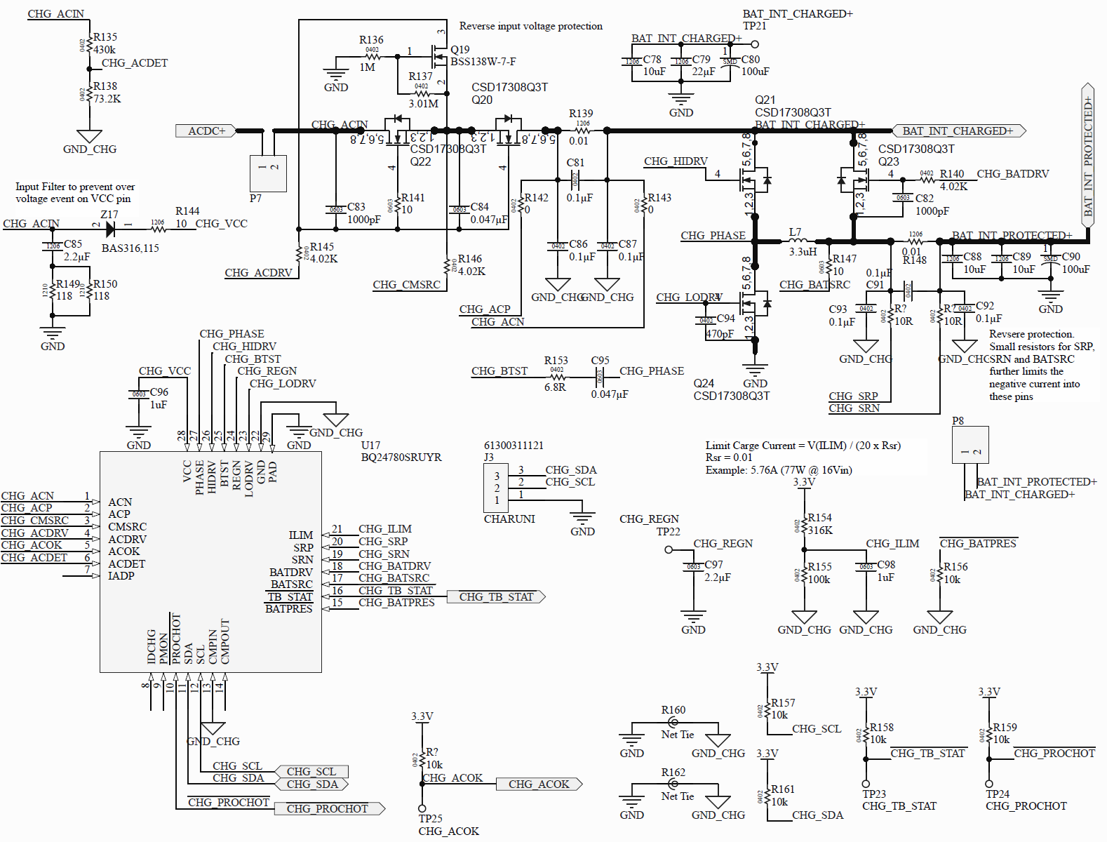
A circuit is designed based on BQ24780S EVM.

During testing, when the user connect the battery incorrectly (reverse polarity) the IC get damaged including some of the external FET.

Once all FET and IC are replaced, the circuit work again. 

A reverse polarity test was performed with a power supply (with current controlled) and the results were similar, the power supply current was same as the maximum allowed by the device.

The design is using the suggested resistors for SRP, SRN and BATSRC.

Please, may I know if the BQ24780S have protection for reverse battery connection? Or perhaps, the design is missing something?

Thanks

  • I missed this comment/image in the question.

    The datasheet mentions this protection, however it seem is not working as expected. 

  • Hi,

    What kind of battery are you using, and how long did you leave it connected in reverse before the IC and FETs were damaged? Also, did you have an adapter connected when you inserted the battery in reverse?

    Best regards,

    Angelo

  • Hi Angelo,

    Below the answer to your questions:

    • The battery is Lithium Polymer Battery with nominal voltage and capacity of 12.8V and 7000mAh respectively. 
    • Once I connect the battery, an spark is cause in the circuit. 
    • The adapter is connected during the testing. 

    Thanks for any advice or suggestion

  • Hi,

    Thanks for answering those questions.

    The reverse battery protection on the BQ24780S is not intended to protect against a battery being connected in reverse for a long time. We expect that the battery pack also has its own overcurrent protection that kicks in about 0.5-1 ms after the battery is connected in reverse. The BQ24780S protection features described in Section 8.2.2.1 of the datasheet are only meant to protect the device during this brief 0.5-1 ms interval before the battery pack's protection kicks in.

    Also, your 10 Ω SRP and SRN resistors are only a 0402 package. We recommend a 0603 package instead, which is what we use on our EVMs.

    Best regards,

    Angelo

  • Hi Angelo, thanks for the clarifications and suggestion about the resistors.

  • Hello Angel,

    I'm having troubles protecting the BQ24780 from reverse polarity connections and I appreciated you could suggest a circuit in order to prevent damaged during reverse polarity connection.

    1. Polyfuse + clamp diode [no tested]
    2. NMOS FET in the Ground Return Path [no tested]
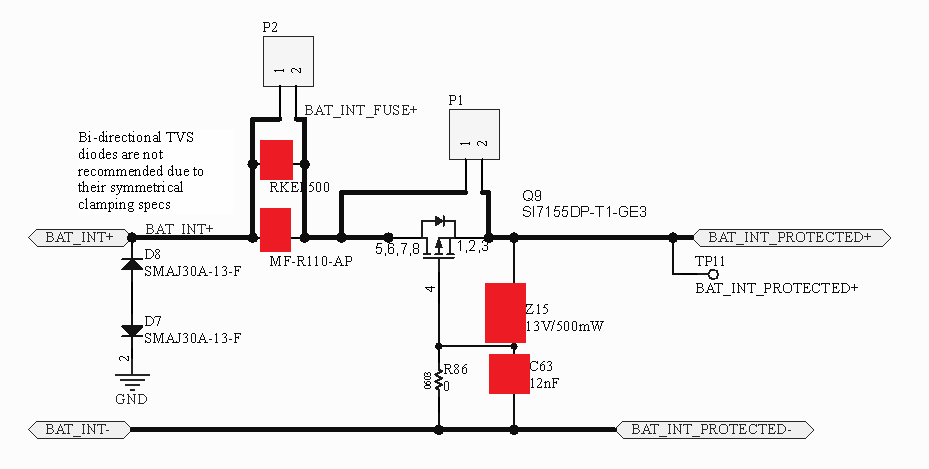
    3. PMOS FET in the Power Path [I have one PCB sample where this solution is not working as expected
    4. LM74610 [doesn't allow to charge the battery]
    5. Other solution involving other parts and/or with the internal FET switch used by the charger?

    Below is the item #3 used without good results. No quite sure the problem come from the board or design integration with the BQ24780S.

    Appreciated any suggestion or help,

    Thanks

  • Hi,

    If your battery pack does not have its own protection, then you can use one of the external battery pack protection methods described in this app note:

    http://www.ti.com/lit/an/slva139/slva139.pdf

    It sounds like you've already tried adding a PMOS in the power path, but that solution isn't working as expected. Can you please provide some more details about how the PMOS solution isn't working?

    Best regards,

    Angelo

  • Hi Angelo,

    Thanks for your feedback.

    I already reviewed the application note suggested. Based on that I used the PMOS approach described in the previous post. In summary, I added the following circuit before the charger:

    In other hand, here mentions that the circuit is not enough for BQ24075. Please, may I know which approach(s) are suggested in order to protect the load, charger  and the battery, when a lead acid battery is connected incorrectly. 

    Thanks

  • Hi,

    I think there's some confusion about the type of reverse battery protection you're looking for. Let me try to clarify:

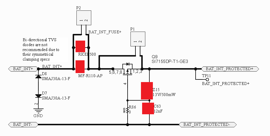
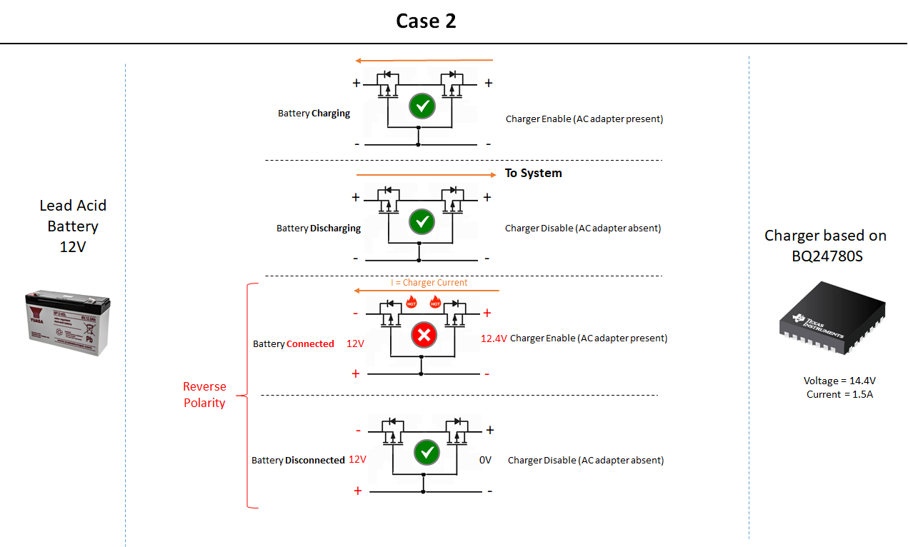
    The single PMOS solution described in the app note (shown below for reference) provides reverse battery protection in one direction. If the battery is plugged in backwards, then current cannot flow from the load into the battery. This is because when the battery is plugged in backwards, the gate voltage is high, preventing the FET from turning on. The direction of the body diode also blocks current from flowing from the load to the battery when the FET is off.

    If you want the reverse battery protection to work in both directions, then you can add another FET in series with the PMOS, but with the body diode facing the opposite direction. This is what Jing is referring to in the E2E thread you mentioned. Since the two body diodes would be facing opposite directions, then current cannot flow in either direction (battery to load or load to battery) while the FETs are off. The battery and the load would only be connected when the battery is plugged in correctly, causing both FETs to turn on and shorting out the body diodes.

    Best regards,

    Angelo

  • Hi Angelo,

    Thanks for your suggestion and feedback. 

    Please, may you confirm the the proposed approach with the following circuit

    Thanks

  • Hi,

    Yes, your diagram looks fine. However, keep in mind that we haven't evaluated this solution on the bench, so please be sure to test this yourself.

    Best regards,

    Angelo

  • Hi Angelo,

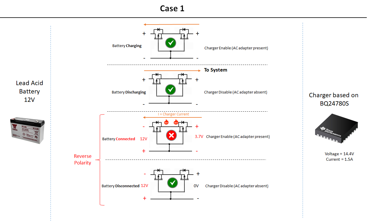
    Just to let you know various testing were performed and still without a proper solution. When the battery is connected in reverse while the charger is enabled is not working.

    Appreciated any advice in order to fulfill the scenarios below.

    Thanks

  • Hi , please, may you take a look to the previous comments? Thanks

  • Hi,

    One thing you could try is adding a NMOS and a resistor in the configuration shown below:

    The logic behind this circuit is as follows:

    1) When the battery is inserted correctly, the NMOS will be turned on by the positive Vgs. The two PFETs will then be turned on by the negative Vgs, thus connecting the battery to the charger.

    2) When the battery is inserted backwards, the NMOS will stay off due to the negative Vgs. The two PFETs will then have the charger's output voltage on their gates, so they will stay off and isolate the battery from the charger.

    In simulation, this circuit seems to successfully provide bidirectional reverse battery protection when charging is enabled. However, it's difficult to model your exact FETs and battery, so again, please be sure to test this yourself.

    Also, please take a look at this app note, which discusses various methods of achieving bidirectional protection. The circuit above is based on Figure 12, and the rest of the app note may also be helpful to you:

    http://www.ti.com/lit/an/slva948/slva948.pdf

    Best regards,

    Angelo

  • Hi Angelo,

    I added the NMOS as suggested. Unfortunately, the results are similar.

    Perhaps, something goes wrong during the test.

    In order to validate this approach, I just purchased new parts (PMOS) and I will test again. I will keep you updated.

    Thanks again for your support in this matter

  • Hi,

    Would it be possible for you to provide a waveform with the following signals the moment that the battery is plugged in backwards? Referring back to the last diagram I sent, the signals I'm interested in are Charger, VBAT, the PFET gate voltage, and the current through the PFETs.

    This waveform would help show what exactly is going wrong and what modifications should be made.

    Best regards,

    Angelo