


Hi,
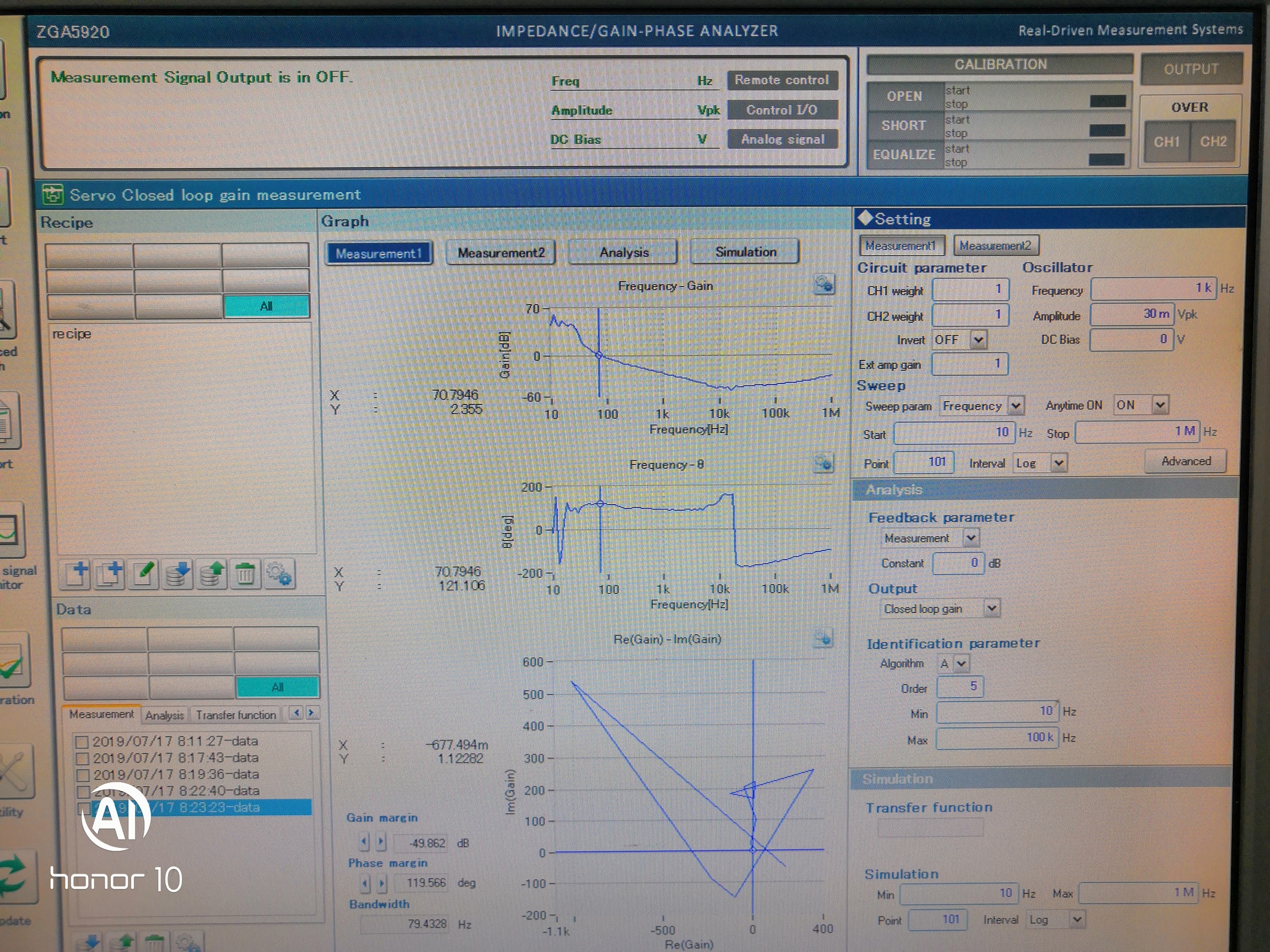
My customer measured the bode plot of TPS7A8001EVM when Vin=3.3V and Vout=1.8V. They found the bandwidth is only 100Hz. But LDO is supposed to have larger bandwidth. Could you help check it?
Thanks.
Hi,
My customer measured the bode plot of TPS7A8001EVM when Vin=3.3V and Vout=1.8V. They found the bandwidth is only 100Hz. But LDO is supposed to have larger bandwidth. Could you help check it?
Thanks.


