This thread has been locked.

If you have a related question, please click the "Ask a related question" button in the top right corner. The newly created question will be automatically linked to this question.

TPS2421-2: output inrush current caused by delay between Vin rising and EN rising when hot swap by Vin

Part Number: TPS2421-2
Other Parts Discussed in Thread: TPS25982

Hi,

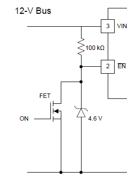
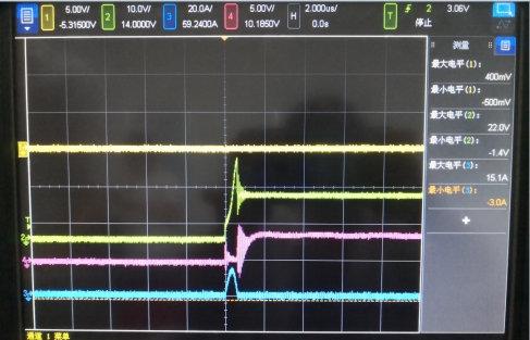
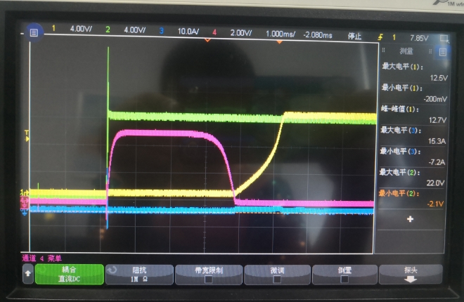
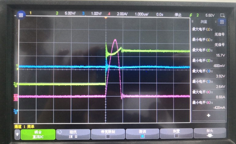
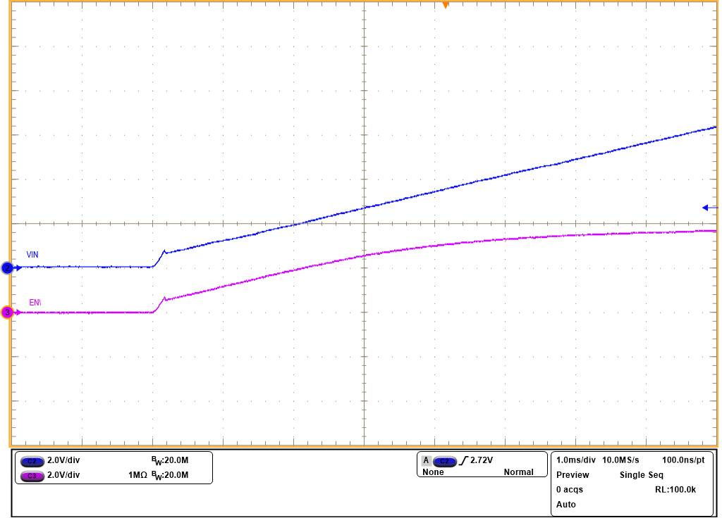
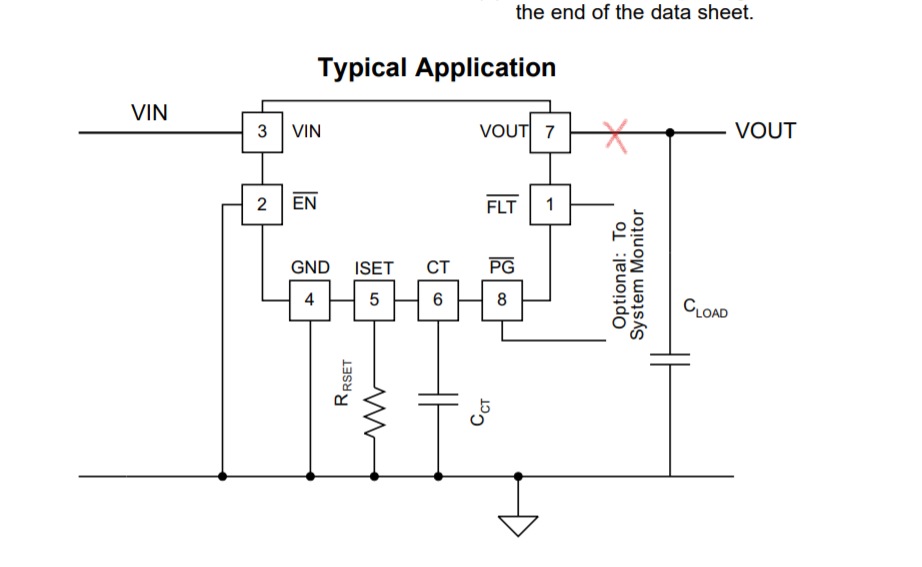
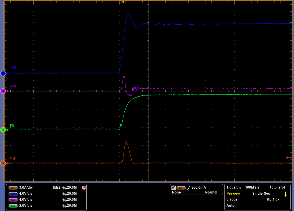
Below is the schematic. My customer would like to keep TPS2421 disabled by EN=high until pulling EN low by the FET. But during hot swap, they found there is delay between Vin and EN, so the EN remain low for a short time which enable the output. We can see the output inrush current during this short time (Green is Vin=12V, purple is EN, blue is output current). When we directly connected EN to the Vin through a resistor(remove the Zener diode), we also saw the inrush current caused by the delay between Vin rising and EN rising. Do we have any method to improve this?

Thanks.

  • HI Jerry,

    Have you checked if the EN/ is following VIN when the FET and zener both are not present ? Please check this to see if the delay is caused by the FET.

    Remember to not apply Vin not more than 5V during this test.

    Also, the time scale of the graph is 2.0 us / div, right?

  • Hi Jerry,

    I haven't heard from you for long. Hope your issue is solved.

    Please reply to this post in case you still face the issue. Otherwise please close this thread. 

  • Hi Praveen,

    After removing the external pull-up resistor and the MOSFET, the delay still exists between VIN and EN.  (Green is Vin=12V, purple is EN, blue is output current).

    Thanks.

  • Hi Jerry,

    I will check this in lab on EVM and let your know my observations in a couple of days. 

  • Hi Jerry,

    Without pullup resistor in your circuit, how can voltage at EN be equal to 4.6V ?

    Aslo, can you please share a waveform zoomed in where you see delay between VIN and EN. 

  • Hi Preveen,

    Customer did a test without any component on EN. EN was pulled up by a constant 3.3V(CH3 blue), VIN is powered up from 0V to 12V(CH2 green). They can see the input inrush current (with CH4 purple). This inrush current is the main concern in this post which should be removed by tps2421.

    Could you check it on the EVM? If it is a bug of TPS2421, I will ask them to switch to TPS25982.

    Thanks.

  • Hi Jerry,

    Thanks for sharing this waveform. This current can be the inrush current in to the input capacitance.

    • How much is the input capacitance on the system?
    • Are your measuring current flowing into the capacitance as well ? Try measuring current without any input cap/ current at the output of TPS2421 (before output cap)/ remove all input caps and then measure the current at the input.  

    I will check this in Lab and get back to you tomorrow with my observations. 

  • Hi Jerry,

    Please see my test results below,

    On the EVM, I have removed C1 and C2 and populated R6 with 33k to make a circuit similar to that of yours. As you can see from the waveform below, I dont see any delay in the EN/ signal raising with respect to Vin.

    Hence, you can be pretty sure that the initial current is into the input capacitors and not flowing into TPS2421.

  • Hi Praveen,

    Could you pls also check the output current? Below is the zoom-in waveform with all Cin removed. CH2: Green VIN, CH4:Purple EN, CH1: Yellow VOUT, CH3: Blue Iout. the main concern of customer is the inrush current of Iout.

    Thanks.

  • Hi Jerry,

    Can you help me understand where exactly customer has measured the output current. Is it before output capacitors as marked below. 

    How did they measure the current at this point ?

  • Hi Praveen,

    Yes, they used a cable between Vout pin and the capacitor. In your test, the rising slew rate of VIN is too slow, so you didn't see the inrush current of output. It is the same in customer's board. You could increase the slew rate of VIN to make the startup time below 1uS as shown in my screenshot, then you could check the inrush current.

  • Hi Praveen,

    Yes, customer replace the Vout PCB trace with a cable for the current probe. In your test, the slew rate of VIN is slow, so there is no inrush current on output. It is the same on customer's board. You could see in customer's test the startup time of VIN is below 1us. Could you pls also take a look at this startup condition? DO we have the explanation?

    Thanks.

  • Hi Praveen,

    Yes, customer replace the Vout PCB trace with a cable for the current probe. In your test, the slew rate of VIN is slow, so there is no inrush current on output. It is the same on customer's board. You could see in customer's test the startup time of VIN is below 1us. Could you pls also take a look at this startup condition? Could we try to explain it?

    Thanks.

  • Hi Jerry,

    I will test this in lab tomorrow with a fast vin slew rate and let you know my observations.

  • Hi Jerry,

    I have tested this in lab today. Below is the waveform that I captured with Fast rising Vin.

    As you can see, the EN pin rises along with VIN without any delay. 

    I measured the output current before the Output Capacitance and I observed some current spike. This current is because of the Cds capacitor and not because of the current flowing in the channel  of the FET (due to EN and Gate).

    As you know for high frequencies capacitor has low impedance, due to the fast rising Vin, the capacitor Cds acted as a low impedance and allowed some current through it. This behavior can be expected in any Mosfet and hence in any efuse.