This thread has been locked.

If you have a related question, please click the "Ask a related question" button in the top right corner. The newly created question will be automatically linked to this question.

LM5110: LM5110 Bipolar Driving ground-referenced Coil

Part Number: LM5110
Other Parts Discussed in Thread: UCC27525

While entering in my question, I saw the problem. So I'm really asking for a potential part or solution.

The LM5110 datasheet only refers to driving N-CH MOSFETS.

I wanted to use the LM5110 with bipolar power supplies to drive a ground referenced coil. 

The N-CHANNEL MOSFET and a P-CH MOSFET short out the power supply due to the DIODES across both MOSFETS.

H-Bridges are typically single supply.

Might you have a part that would allow bipolar drive?

Thanks

Peter

Coil Driver+qa_V1.pdf

  • Hello Peter, 

    Thanks for your interest in our driver, my name is Mamadou Diallo from the High Power Drivers team.

    I have few comments/questions before addressing your questions.

    Can you help me understand why specifically you need the bipolar supply to drive the N-ch FET? Do you really need a bipolar supply? 

    LM5110 is a good starting point as it allows to implement (if really needed) a dual power supply to drive the FETs. Our drivers can be used to drive to P-channel FETs as well by using LM5110-3SD where the inverting channel (CH-B) can be used to drive the P-Channel FET while the non-inverting drives the N-channel. 

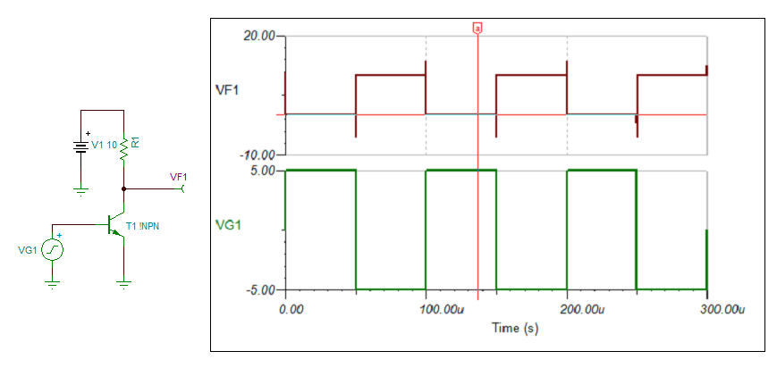
    You can also use the SOIC package version (both channels inverting or Non-inverting) and implement a inverter circuit using a discrete npn at the drivers' input as shown below.


    However, if the bipolar supply is not necessary, then I suggest you to consider the UCC2752x family from our low-side driver portfolio specifically UCC27525 which has an inverting and non-inverting channel as well as a higher operating supply range 20V (vs 15V for the LM5110). 

    These drivers do not have dead-time time features so you would have to implement this externally on the controller.

    Additionally, I am not sure what your desired response time is (from Driver + FETs) but the series gate resistances R21 and R28 of 100-Ohms will significantly reduce the turn-on/off of the FETs. You may need to tune this value to control the rise/fall times at the gates of the FETs. The link below discusses how to accomplish this.

    Please let us know if you have further questions or press the green button if this resolved your inquiry.

    Regards,

    -Mamadou

  • Thanks for the response.

    A decision was made to scrap that approach to the task.

    A simpler solution has been decided upon.

    Regards

    Peter