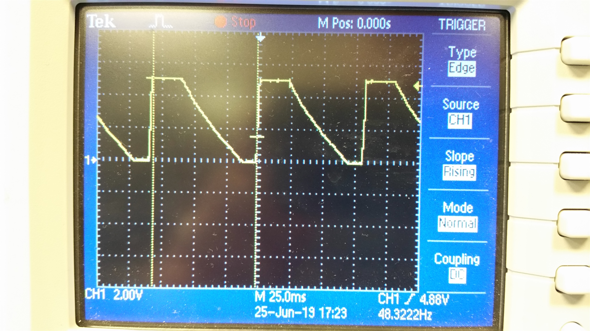
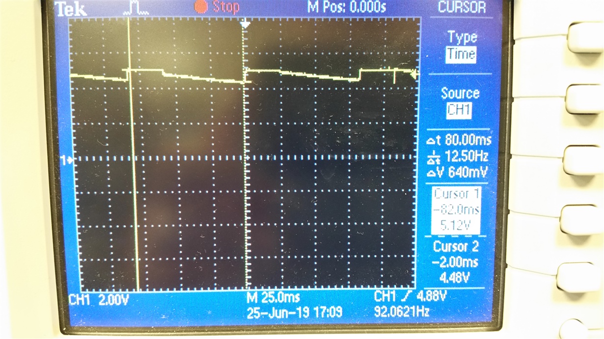
PTH12000W is configured for 5 V output. Most units operate properly. At least 2 units have failed, with the output toggling rail-to-tail with a period of ~ 80 ms.
This thread has been locked.
If you have a related question, please click the "Ask a related question" button in the top right corner. The newly created question will be automatically linked to this question.
PTH12000W is configured for 5 V output. Most units operate properly. At least 2 units have failed, with the output toggling rail-to-tail with a period of ~ 80 ms.
Hi Carl,
It seems as if the device is going into an over-current protection. Can you provide more information on your condition? Are you running the module at maximum output current? I would like to run some tests on my bench and see if I can replicate the behavior.
Thanks,
Alejandro
Hi Alejandro:
I also thought that this might be an overcurrent response. But the waveform shown was taken with a 10 mA load. I also measured the unit without any external load. I have two units that are behaving similarly. Could there be some damage so that the overcurrent detection is always active?
Hi Carl,
I did some tests on my bench at various loads and the module did not display any abnormal behavior like the waveforms you have provided. I have the following set up:
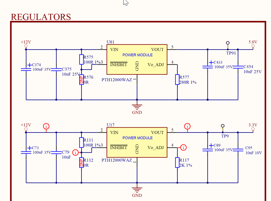
Can you please share your application schematic? The input and output components? Plus, any inhibit components?
Thanks,
Alejandro
Hi Alejandro:
I don't think that the problem will shown up for you if you just replicated our setup. We have hundreds of units built, and only 2 are showing the problem. But, in the mean time, this is our application circuit. The issue on the two units is with the regulator shown as U81. A near-identical instantiation, U17 (Set for 3.3. V) works correctly on the same module where the U81 (set for 5.0 V) is failing.
Any insight on possible failure modes would be appreciated.
Thanks,
Carl W.
Hi Carl,
The PTH12000W output voltage may drop periodically when no prebias voltage is present on the VOUT node, because the device actively controls for prebiased output at startup. This function controls the high side power FET for the first ~20ms; this delay insures the module does not sink current from the output bus to ground. The pre-bias transition control from high side FET to continuous low side FET sinking current is the voltage sag (as shown on your waveforms provided).
When VOUT is lightly loaded, a negative pulse from the regulated output voltage can be present at the ~20ms with varying decreasing levels.
Huge capacitance and component quantity on VOUT can cause slow feedback response, causing unstable out, therefore going into over current protection.
Regards,
Alejandro
Hi Alejandro:
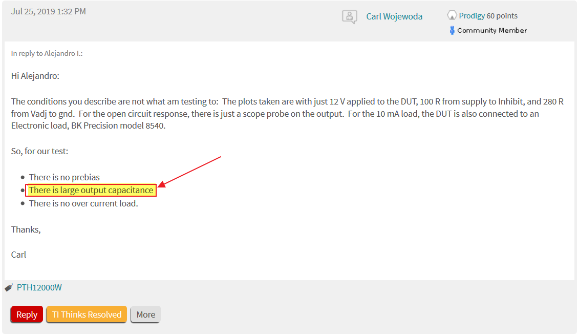
The conditions you describe are not what am testing to: The plots taken are with just 12 V applied to the DUT, 100 R from supply to Inhibit, and 280 R from Vadj to gnd. For the open circuit response, there is just a scope probe on the output. For the 10 mA load, the DUT is also connected to an Electronic load, BK Precision model 8540.
So, for our test:
Thanks,
Carl
Hi Carl,
Looks like the large output capacitance can be the root cause (the large output capacitance can be slowing down your feedback response). Are you able to lower the output caps on your current application? Take a look at Page 8 in the datasheet which indicates recommended input and output capacitors.
Can you provide more information of your output capacitors? ESR Ratings? Vendor Part#?
Lets also look at one more thing: Can you provide a scope shot of Vout and Input current under no load and a light load 10mA condition?
Thanks,
Alejandro
Hi Alejandro:
As I said in the previous posting, the plots that were taken were taken WITH NO EXTERNAL CAPACITANCE. I cannot lower the capacitance below nothing. And, again, these are two units out of several hundred that are having trouble. We are fairly confident that the application is correct.
For reference, the output capacitors are: Nichicon UCL1V101MNL1GS and parallel Murata GRT188R61E106ME13D. The input capacitors are the same two capacitors in parallel.
I will take the Vo / Input current measurements and reply with those tomorrow.
Hi Carl,
Let's start by ensuring we are looking at the same concern and get a clear understanding of your application.
About two of your modules are experiencing failures. The scope shots provided are with no external load and a light load of 10mA. Also, there are no output caps connected when testing (taking waveforms), even though your application schematic shows output caps connected and only an indication of 'without an external load' in previous posts. Also, safe to say, what you stated previously (see image below) was a typo.
Okay, we'll take a look at those waveforms and continue to solve this phenomenon.
Regards,
Alejandro
Hi Alejandro:
You are correct, that was a typo in my earlier statement; I meant to have said "Their is no large output capacitance". In the plots attached, the yellow trace is the output voltage, and the cyan trace is the input current. The input current shows a small ramp during the output voltage ramp up, likely due to the charging of the on-module capacitors.
There is a large input current pulse right when the output collapses. This makes me wonder if it is possible that the dead time control has failed and both switches are both on simultaneously. This might be the cause of the input current pulse, and might trigger the over current detection. Does that sound possible?
It really does sound that these modules have failed -- how can we submit these units for Failure Analysis?
Thanks,
Carl
Hi Carl,
Certainly; contact me directly at a-iraheta@ti.com
Regards,
Alejandro
Hi Carl,
I have not heard back from you. I'm going to close the thread due to inactivity. But, please contact me directly at a-iraheta@ti.com if you would like to submit the modules for a failure analysis.
Regards,
Alejandro