This thread has been locked.

If you have a related question, please click the "Ask a related question" button in the top right corner. The newly created question will be automatically linked to this question.

UC1543: U.V Electronic symbol and circuit application

Part Number: UC1543

Hi Team,

I am posting this in behalf of our customer:

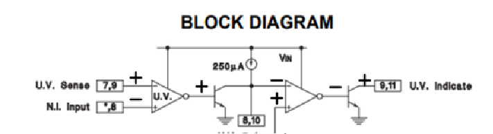
1. Our customer would like to confirm what is the name of the symbol below in the block diagram of U.V. Sense and N.I. Input of UC1543:

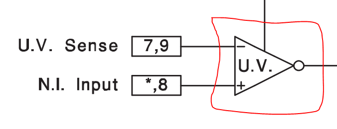
2. When U.V. Sense voltage is above N.I. Input, does the U.V. Indicate voltage go to Vin and if the U.V. Sense voltage is below N.I. Input, does the U.V. Indicate voltage go to 0V. 

Thanks,

Jonathan

  • Hey Johnathan,

    1. I'm unsure what you mean by "name of symbol". Its a comparator with an inverted output.

    2. This answer had to be correct please see below.

    Thanks,

    Daniel

  • Hi Daniel,

    Thank you very much for your answers. However, our customer has follow up questions below:

    1. If the U.V. Sense is below the N.I. Input, does U.V. Indicate go to Vin?
    2. The Out-Of-Tolerance Indicators (In Figure 7 on page 6), they are connected to a Bias Supply. Are the Indicators connected to ground of the Bias Supply?
    3. Basically, if the U.V. Sense is above the N.I. Input, the U.V. Indicate is driven to ground therefore is the Indicator on or off?

    The 1st question is considered resolved so I am very thankful for your answer.

    Regards,

    Jonathan

  • Hey Jonathan,

    1. U.V. will go high impedance. Adding a resistor to Vin obviously will allow the pin to go to Vin in this case.

    2. In figures 7 and 8 the indicators are connected to the ground of the supply by pin 14 the ground of the device.

    3. The indicator will be driven to ground, but whether or not that means on or off in up to the circuit design and the logic downstream of the device. I imagine that the most common way of doing it is the output is in HiZ for most of the time unless there is a U.V. indicator in which is pulls the pin of a comparator low.

    Thanks,

    Daniel

  • Hi,

    I have some questions about this image. I understand this image shows a comparator with an inverted output. That is how I see it as well.

    But this is how I understand this part of the schematic.

    If the U.V. Sense voltage, inverted input, is greater than the N.I. Input, non-inverted input, the comparator goes low or -Vcc. Then the inverted output takes it high or +Vcc.

    Please help!

    Regards,

    Cole

  • Hey Cole,

    I believe I misinterpreted things.

    In a normal configuration the OP AMP will go low when the negative input is higher than the positive input. Since it is inverted, we see the opposite. Thus you are correct.

    Unfortunately this ends up changing the way the output will go:

    This means U.V going high causes the output to go high.

    Thanks,

    Daniel