This thread has been locked.

If you have a related question, please click the "Ask a related question" button in the top right corner. The newly created question will be automatically linked to this question.

BQ25886: Standalone 2 Li Ion Battery Charging through USB

Part Number: BQ25886

Hello,

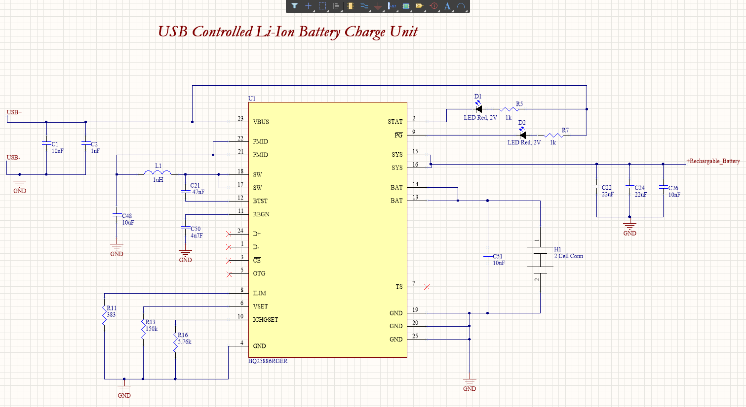
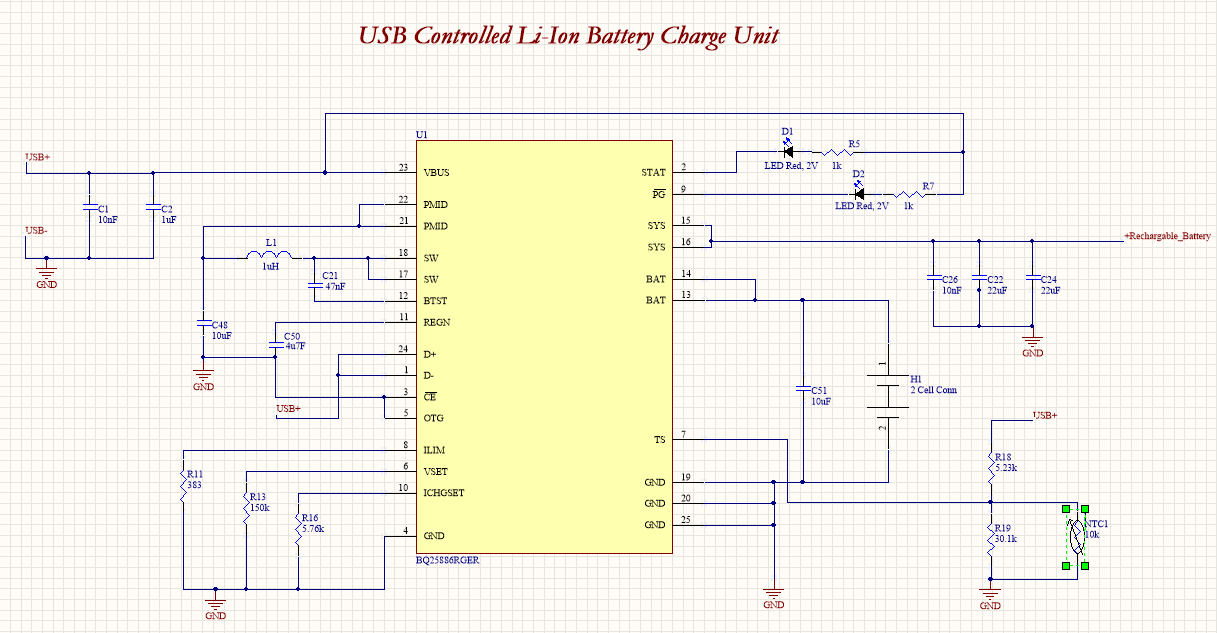
I will power my custom PCB with two serial connected 3.7 V Li Ion batteries. I have extra battery monitoring circuit. My target with BQ25886 is that charging the two serial batteries via USB port without the switch off my circuit.  I have designed with Altium. So I have couple of questions:

1. Did you see any mistake in the design. If there is, could you share your thoughts?

2. Space is important on my design. Based on the evaluation board design, the designer prefered 1uH inductor with 11A saturation current. But this is really big for my case. So I selected 1 uH with 2.5 A saturation current. It will be a problem? 

3. I plan to use this IC as a standalone, so I didn't connect D+/D-/CE/OTG pins anywhere. Do you think it is fine?

4. I don't have thermistor and I don't know the thermistor connection for the battery. So I didn't connect anywhere the TS pin. Do you think it is fine?

5. 'Rechargeable battery' label is input power line for my regulators. So I connected SYS pins to the regulators with 22uF and 10nF capacitors. Do you think it is true approach? 

During the design, I refer to the IC's evalution board design and datasheet.

Thank you,

  • Alpaslan,


    • I would recommend an inductor with a rating of at least 150% of your maximum input current. This should account for most ripple and possible current surge that may occur during transients. In your case, I would look for a 1 uH inductor rated for at least 5 A saturation current.


    • /CE should be pulled low to GND to enable charging.

    • D+/D- are used to detect the appropriate input current limit of the USB adapter. To use D+/D-, connect these pins to the D+/D- pins of your USB adapter. You can short D+/D- together to allow for the highest 3.0 A input current setting and limit the current using the ILIM pin as you have.

    • If you do not plan to use OTG, pull it low to disable the functionality.


    • The TS Resistor Network shown in Figure 18 is required. If you do not plan to implement a thermistor, you can use the resistor values described in 8.3.7.4.1 in the datasheet (RT1 = 5.24k, RT2 = 30.31k) and use a fixed 10k resistor in place of the thermistor


    • Your SYS pin design is correct, but please place the 10 nF capacitor closest to the IC before the 22uF capacitors. Ideally, place the capacitors as close as possible to the IC.


    Thanks,

    Ricardo

  • Hi Ricardo,

    Thank you for the reply to my message and clear explanation!

    I selected 1uH with 7A saturation and 6.5A ripple current. It's part number is MPIA4020V2-1R0-R. 

    I pull down the CE and OTG pins with connecting to the ground. I pull up D+/D- with connecting USB line. 

    I connected SMD NTC resistors (B57330V2103F260) as a parallel to 30.1k. In the datasheet, the thermistor recommended as through-hole type one. But I prefered SMD package. 

    My last question is that without charging through USB, the batteries will supply the power to my circuit, won't they?

    Also, I updated my design, could you check it?

    Thank you

  • Alpaslan,


    Here are my thoughts on your updated schematic:

    • That inductor should work for your application
    • The CE and OTG pins are configured properly based on the your needs
    • D+/D- should be connected to the D+/D- pins of your USB port respectively. There are four pins on a USB port: VCC (VBUS), D-,D+, and GND. The order of the pins varies based on the type of USB connector you select, so please verify that.
    • The SMD thermistor you selected is acceptable for you circuit
    • When the adapter is disconnected and a battery is connected, the circuit will be powered from the battery.

    Thanks,

    Ricardo

  • Thank you, Ricardo! I updated my design based on your feedback.

  • Hello Ricardo,

    In the BQ25886 datasheet, NC pin is specified in the pin functions table and represented with 1st pin. But the 1st pin is at the same time D- pin, so which one is true?

    Thank you,

    bq25886.pdf

  • Alpaslan,


    Thank you for bringing this to our attention! D- is pin 1 and the description for it is accurate. The NC pin description should not be there at all. We will update this in our next revision.


    Sorry for any confusion,

    Ricardo

  • No problem! TI Support in this forum within different topics helps me a lot. If I see any missing points, I will inform you every time.