


Hi,
1. datasheet page 20: -3V threshold voltage of VEE UVLO, with 400mV hysteresis. Does this mean VEE have to be lower than -3V?
I am at circuit design stage. First I used the power supply which can provide 20V and -5V, which is good for this driver. Then I found out the max. Vgs of our Infineon SiC MOSFET is 20V so I have to use 15V for VDD and the corresponding VEE is -3V. I come back to check this driver and found out UVLO VEE of this driver is -3V. We already bought this drivers and Infineon devices and had to use it. If VEE must be lower than -3V, I have to find another power supply.
2. datasheet page 3: RST/EN serves two purposes. Can I use this at the same time for this two purposes or only can choose one?
a. Enable or shutdown the driver, no driving outputs.
b. Reset the fault signaled on FLT pin.
so when it is active low, the FLT signal is clear and driver is disabled? I am confused.
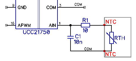
3. datasheet page 24: An internal current source IAIN in AIN pin is implemented in the device to bias an external thermal diode or temperature sensing resistor.
please see below. RTH is integrated in SiC MOSFET module in gray block and there are two terminals called NTC.
a. The voltage across the RTH = IAIN *RTH =200uA*5000k=1V if RTH=5kohms. Is this right? If it is right, then RTH requires 2.5kohms to 22.5khoms to meet AIN voltage of 0.5V to 4.5V. Or my schematic is in wrong connection?
b. What is relationship between AIN and APWM? How to monitor the temperature using these pins?
datasheet only provides three special cases at VAIN=0.5V, 2.5V, 4.5V. I can use one case to set the max temperature but can not monitor the temperature.
Thanks,
Hongmei Wan
