This thread has been locked.

If you have a related question, please click the "Ask a related question" button in the top right corner. The newly created question will be automatically linked to this question.

LM5170EVM-BIDIR: LM5170EVM-BIDIR:Circuit Breaker

Part Number: LM5170EVM-BIDIR
Other Parts Discussed in Thread: LM5170

Hi TI engineer,

I have a question about LM5170 evm board.

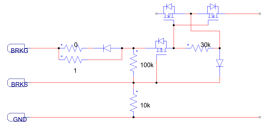
I reworked the reverse circuit from below diagram to against reverse battery polarity.

When I operated in boost mode, I found that the input inrush current is very high at the moment of the Oring MOS turn on.

Please suggest how to change the turn on time and still maintain the turn off time.

  • Hi Steven,

    Thank you for using the LM5170.  Which battery's polarity is reversed?  The above circuit is to protect against the 12V battery reverse polarity, but not the 48V battery.  The dc-dc switch body diodes form the path to conduct the current when the 48V battery polarity is reversed. You need to add a protection circuit for the 48V side, too.

    Can you share some details about your application?  If you don't want to disclose it at e2e, can you reach us through our FAEs in your local area?

    Thanks,

    Youhao Xi,  Applications Engineering

  • Hi Youhao,

    Yes, I know that the above circuit is to protect against the 12V battery reverse polarity.

    When I operate in boost mode, the input inrush curreny path is from LV side (12V) to HV side(48V).

    The input inrush current is up to 116A because the output capacitance(1200uF) is very large.

    As a result, I want to increase the turn on time to reduce inrush current and still maintain the original turn off time.

    Please suggest how to adjust component value of the drive circuit.

  • Hi Steven,

    What you see is basically a hotswap issue.  I believe you applied a high voltage to VIN pin to help turn on the breaker FET, rigtht?  

    To reduce the inrush, you need to turn on the Breaker FETs slowly.  Insert a gate resistor between the BRKG and the FETs' gate, and also add a capacitor across the gate and source of the FETs, then the RC can slow down the turn-on and making it a inrush limiter.

    When you do this, remember to add a diode in parallel with the gate resistor, so the turn-off of the FET is not affected by the gate resistor.

    Hope this clarifies.

    Best Regards,

    Youhao

  • Hi Youhao,

    Yes, I only generate a high voltage to VIN pin  to help turn on the breaker FET by adding a additional circuit.

    I try to increase the 1 Ohm~10 Ohm, but the situation of the inrush current does'n improve. 

    I also add a capacitor across the gate and source of the FETs, and it's a effective way to reduce the inrush current.

    However, the turn off time of the breaker FET is increased, it maybe accompany protection risk.

    Thus, I hope you can suggest other solution except above solutions.

    Thanks.

  • It is the effective solution.  I would use 10kOhm and a small capacitor, and add a diode in parallel to the 10kOhm.  So the turn-off speed will not be affect much because it only requires to discharge a smaller capacitor.  

    Thanks,

    Youhao 

  • 10kOhm?Really?

    This value is very large. 

    Could you seggest how to design Rg value?

    I just try 10kOhm and  it's a effective solution to reduce inrush current.

    However, I find the stable Vgs lower than 10V, it seems to someing mistake occur.

  • You can change it to 2k to reduce the voltage drop, so you can get at least 10V at the FET gate,  and increase the gate capacitance to 5x to have the same delay time. 

    Thanks,

    Youhao