


Hello,
I made a dual output flyback power model following the circuit recommended by the UC3843 manual.
The circuit schematic is similar to the manual recommended circuit. As shown below:

In the actual circuit, Cvref chose 0.1uF. When the power supply is started at no load, the output voltage is overshooted. The waveform is as follows:

channel 1 yellow is the input voltage, channel 2 green is the output voltage, channel 3 blue is the input current, and channel 4 purple is the REF pin voltage. The above picture is partially enlarged, as shown below:
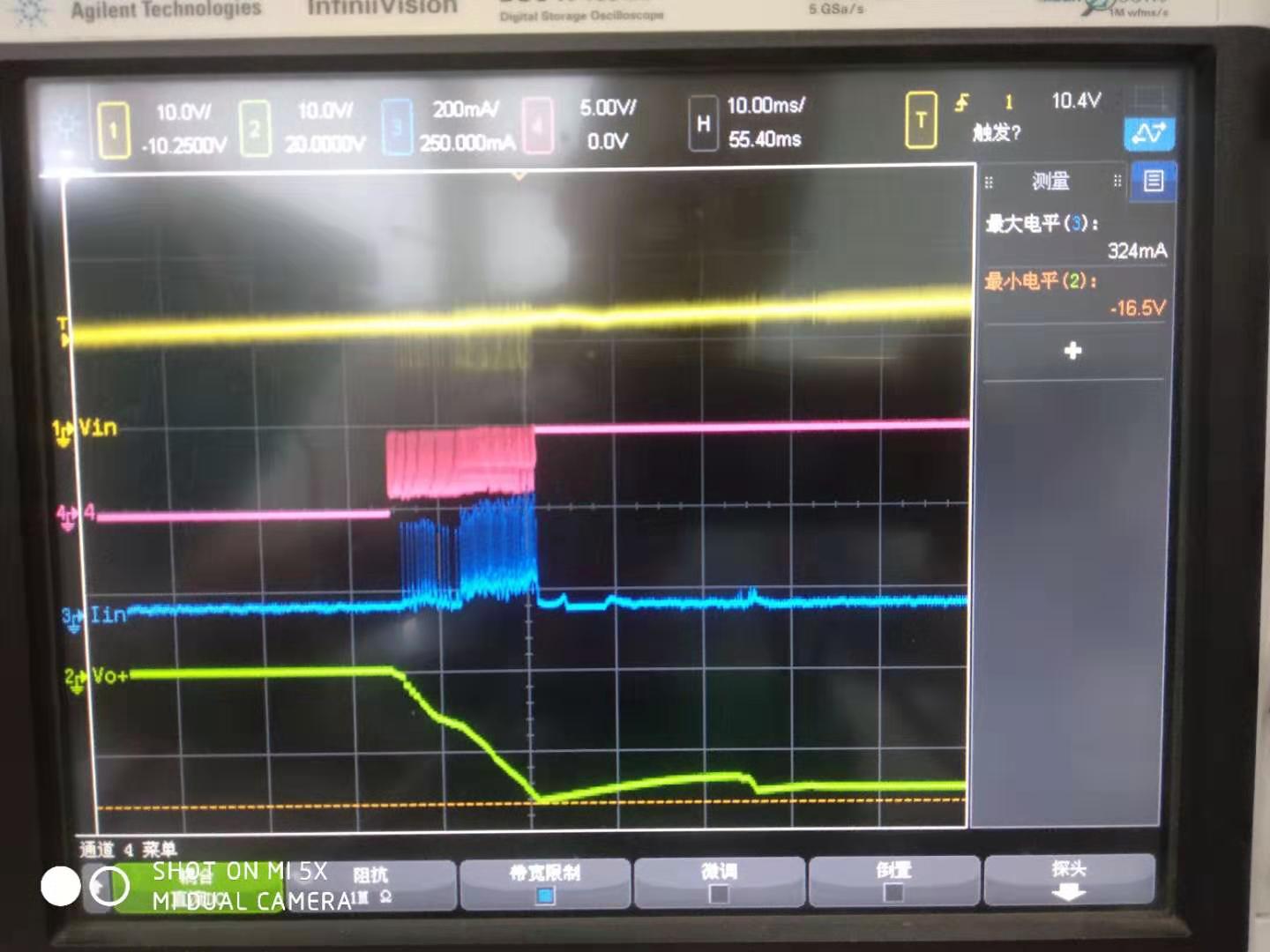
It can be seen that both Iin and Vref oscillate during the period when the power supply no-load output overshoots.
I removed Cref and the power supply no-load output is normal, as shown below:

Partially enlarged view, as follows:
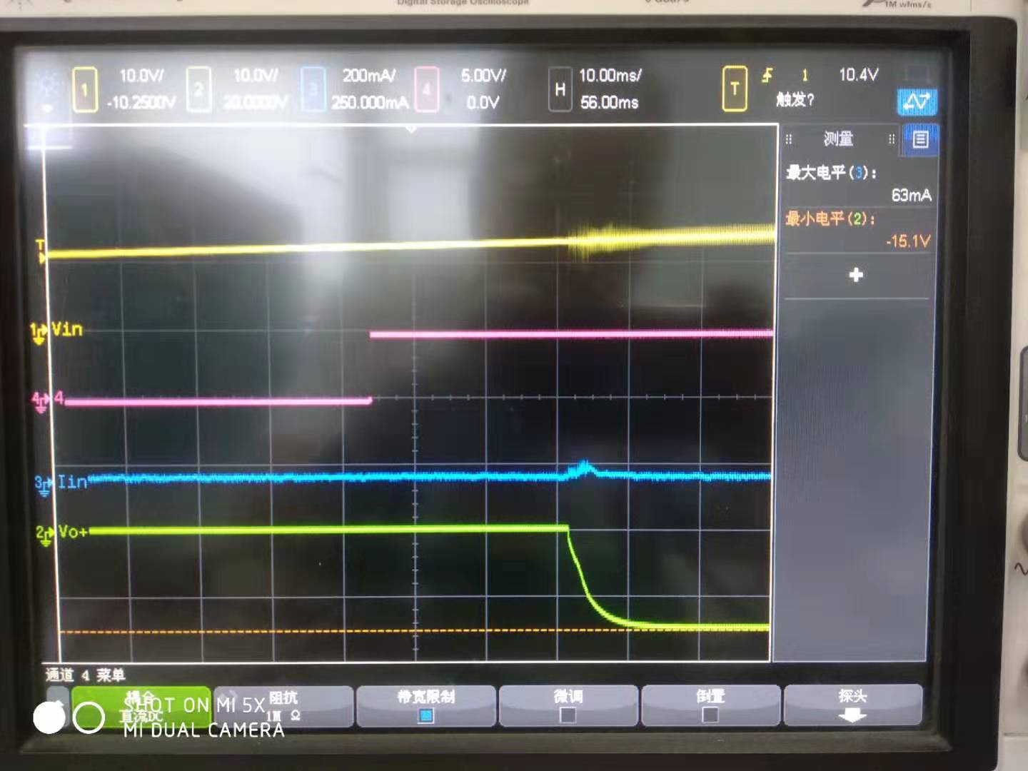
At this point, the REF pin does not oscillate, Iin has no spikes, and the output voltage does not overshoot.
I am very confused, why the power supply is normal after the 0.1uF capacitor of the REF pin is removed, and with the 0.1uF capacitor, the power supply will have an overshoot. What is the reason?
