This thread has been locked.

If you have a related question, please click the "Ask a related question" button in the top right corner. The newly created question will be automatically linked to this question.

LMR23625: How the hiccup mode is detected?

Part Number: LMR23625

Hi Team,

I'm curious about how the LMR23625 detect the current and go into the hiccup mode? Is it a valley current detection of inductor current within the peak current mode? From the datasheet, I can't figure it out clearly. Hope for your professional response.

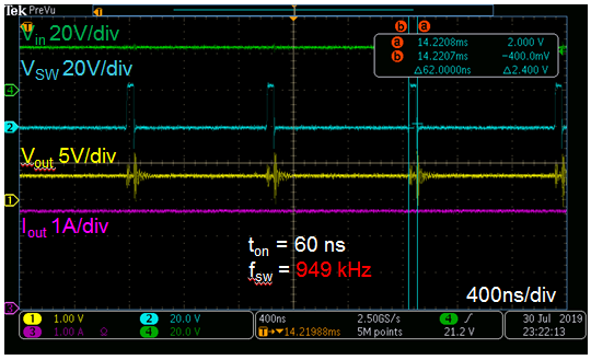
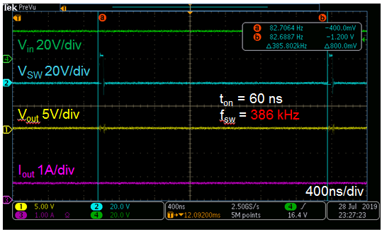
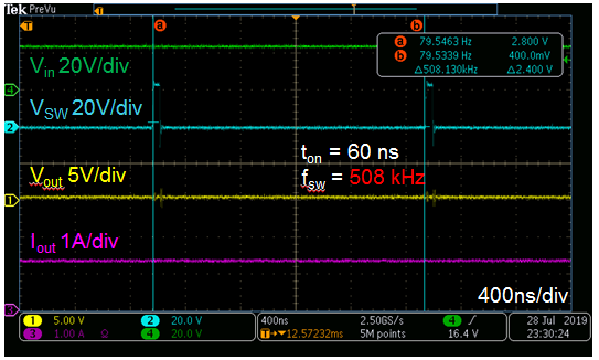
Another question is if the LMR23625 can have a foldback frequency when the Vin go up and hit the ton_min limitation, why can't WEBENCH simulate with such a high Vin?

If there is a detailed materials of mode conversion between PWM and PFM, can you share it to me with my email address:  y-han1@ti.com.

Thanks a lot!

Flora

  • Flora,

    Yes, you can see from the block diagram in the datasheet and the description at the end of section 8.3.8 that the Hiccup Detector block is connected to the Low-Side current sense. The IC senses the low-side current and extends the off-time if the inductor current has not ramped as low as the low-side current limit. The part enters hiccup when the IC must extend this off-time for 64 consecutive clock cycles.

    I will forward this question to the WEBENCH team to answer the WEBENCH question.

    We do not have content specifically for mode conversions for this part. But you can use the datasheet parameters (Ton_min...) to calculate the effective duty cycle for your conditions.

    -Sam

  • Sam,

    Thank you for your professional reply and I'm looking forward to the answer by WEBENCH team.

    Another question is: For HSOIC package, which can enter PFM mode when the load is light, and according to the description in 8.3.4, the activated condition is either the minimum HS switch ON-time (tON_MIN ) or the minimum peak inductor current IPEAK_MIN (300 mA typical) is reached.

    But when Vin is very high, I think the Ton_min will also reached, why it can't activate PFM mode?

    Thanks a lot!

    Flora

  • Hi Flora,

    For higher input voltage when the minimum HS switch ON-time is being hit, the device reduces the switching frequency and enters in the PFM mode. Currently, this feature is not modeled on the WEBENCH for LMR23625. We will fix this and let you know once this issue is resolved.

    Thanks & Regards,

    Praveen B

  • Praveen B,

    Thanks for your reply, and I'm looking forward to hear from you about the process of this issue.

    Flora

  • Sam,

    Here comes a new question, if the IC extends the off-time for 64 consecutive clock cycles to enter hiccup mode, why the frequency continues increasing during the start time with a fixed minimum ton time from my observation on the oscilloscope? The frequency increase from around 300 kHz to 900 kHz. I'm trying to find the start up condition with large capacitive load.

    Thanks a lot !

    Flora

  • Hi Flora,

    There are two things.

    1. The device enters in PFM mode when either minimum on/off time is hit or the minimum peak inductor current IPEAK_MIN (300 mA typical) is reached. The frequency is reduced to increase off time.

    2. The device enters in Hiccup mode if the current of the LS switch is above the LS current limit ILS_LIMIT(3.5A typical) for 64 consecutive cycles.

    Thanks & Regards,

    Praveen B

  • Praveen B,

    Sorry, I can't understand it by now. So I record the waveform when the LS switch shutdown and enter the hiccup mode (Figure.1 & Figure.2). However, from  figure.1, the time for LS switch to shutdown isn't 64 consecutive cycle, which reflects by frequency continuous increasing from 300kHz to 900kHz (figure.3 & figure.4 & figure.1). If the current of LS switch is above the LS current limit for 64 consecutive cycles, the off time must be extended, and the frequency will be decreased. Can you help me finding out the reason? Besides,ton is 60ns during the whole process.

    Thanks a lot !

    Figure.1

    Figure.2

    Figure.3

    Figure.4 

    Flora

  • Flora,

    The IC, from your waveforms, starts with low current, high VIN, and low VOUT. This will fold back the frequency due to the minimum on time of 60ns to achieve the required duty cycle to maintain regulation.

    Increasing the output current will cause the frequency to increase in order to increase the duty cycle since the TON is still 60ns. This provides more output current and will maintain regulation. The on-time is still 60ns because the switching frequency has not increased to your selected switching frequency yet.

    -Sam