principle:
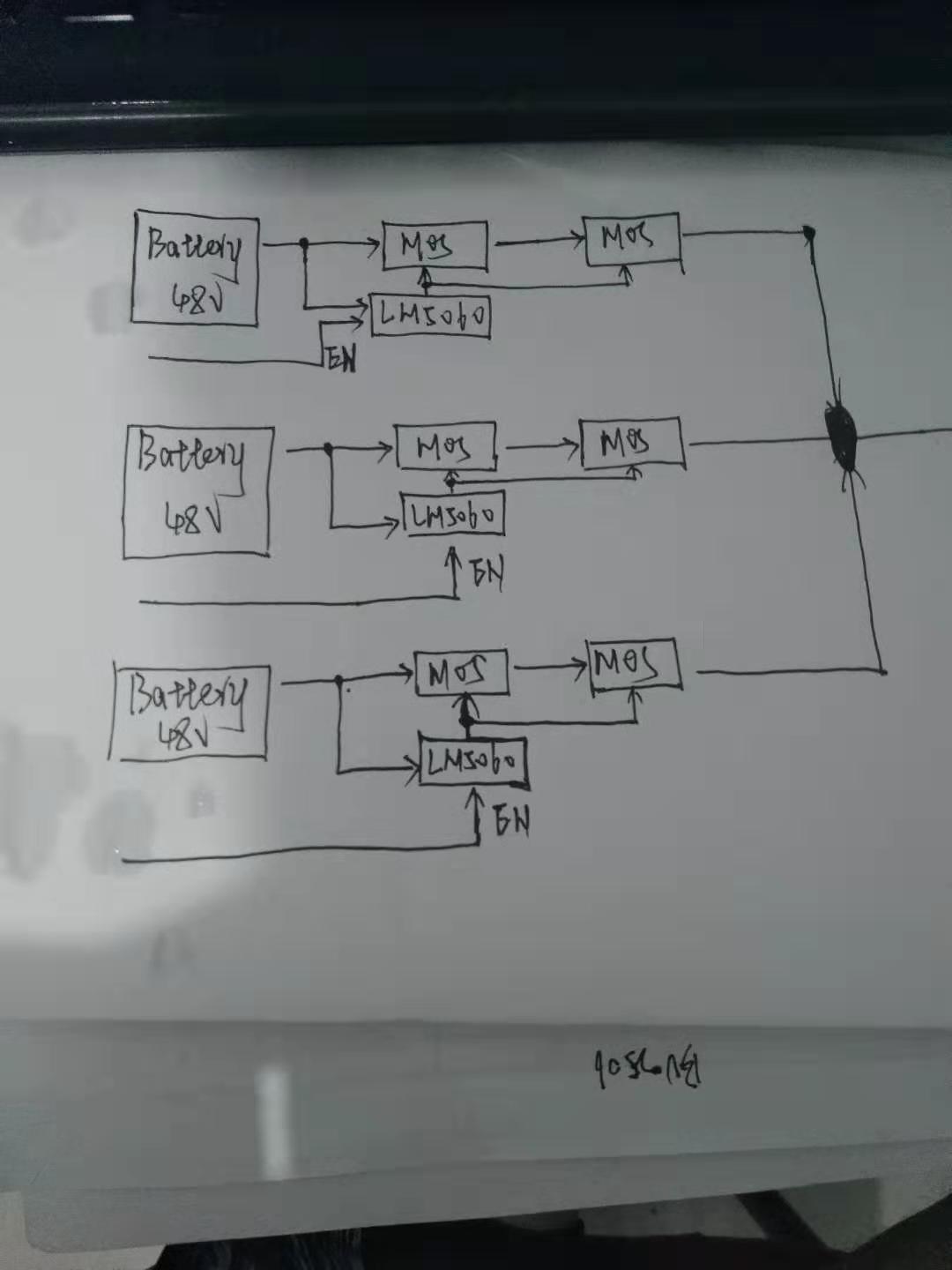
The MCU controls the turn-on and turn-off of the MOS by controlling the EN pin of the LM5060. There is only one battery output at a time.
The picture is the basic principle.Because the paper is limited, only three batteries are drawn.
problem:
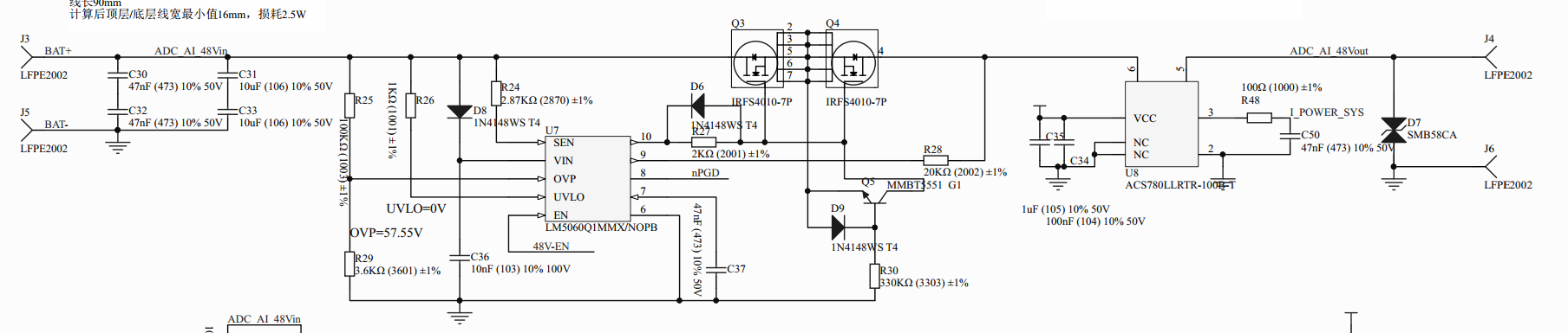
One battery output is turned on and the other battery output is turned off. The LM5060 that shuts down the battery will burn off.
The analysis may be that when the LM5060 turns off the MOS, the G pole of the MOS is about 0V, the GS voltage is -48V,
which exceeds the manual's ±20V, and the GS breaks down and burns the 10-pin GATE of the LM5060.
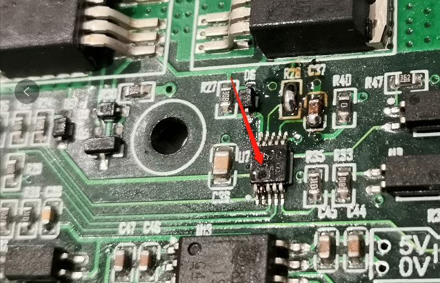
But the picture is a hole burned between the 1 and 2 pins. Please help analyze it?
Our solution is to connect a diode to the back of the MOS, but because the current is 40A, the diode consumes too much power,
and the solution is not very reasonable. Is there a better solution for 4 battery selection outputs?