


Hello,
I would like to design +15V input to -15.5V 2.5A output with External Sync Clk in 1MHz 5V input on LMZM33606.
Quote with datasheet: External Sync Clock signal requirement: Low <=0.4V, High >= 2V and should not higher than 5.5V reference to AGND
When design with Negative output (IBB), I would like to confirm the Sync Clk require to shifting the clock signal level from <0.4V ~ >2V at first main powerup stage down to < -15.1V ~ > -13.5V (not higher than -10V) at the target -15.5V output. Please correct me if wrong.
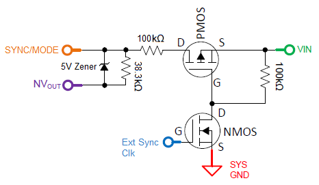
If that is the case, I would like to have below circuitry reference with Enable control circuitry from App Note SNVA835B by adding Zener diode to limit the clock amplitude follow the negative output level. Sorry that I haven't EVB in a short time to try some experience on it, need some valuable input on it.
Sync/Mode pull low (Rrt) with 38.3K is set for initial switching frequency at 1MHz.
If there any better solution and recommendation are welcome.
App Note SNVA835B is very helpful, recommend adding with External Clock application circuitry recommendation.
Thanks in advance for support on this case.
Best regards,
Ping
