This thread has been locked.

If you have a related question, please click the "Ask a related question" button in the top right corner. The newly created question will be automatically linked to this question.

UCC256303: OVP BW pin

Part Number: UCC256303
Other Parts Discussed in Thread: UCC256403

I need an OVP that has a tighter precision than can be obtained by sensing the secondary voltage with a Bias Winding.  Therefore, The OVP level will be monitored by circuits directly at the Output and a separate optocoupler used to send the OVP trigger to the primary side.   This signal must latch off the UCC256303 until its bias power is reset.

Is there a way to use the BW pin to do this?  Perhaps couple the phototransistor thru a charged capacitor to the BW pin to drive it below negative 4V ?   But the diagrams imply that gate drive pulses must be happening during the overvoltage condition in order to repetitively sample the negative voltage on the BW pin.  Is that correct?  

If the OverVoltage comes from an external source (rather than from a broken voltage regulation feedback signal)  the feedback will stop the gate drive, and therefore the OVP sampling.  Correct?

  • Hi R Wagner,

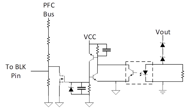
    Thanks for your interest in UCC256303. I would suggest using an opto-coupler circuit to pull down the BLK pin voltage in order to force the controller to stop switching. This would be simpler to implement than trying to achieve a -4V signal on BW. To achieve a latching function, a silicon controlled rectifier can be used on the primary side to keep the BLK held below the stop threshold until VCC is cycled. This method will work with either the UCC256303 or the new UCC256403.

    Silicon controlled rectifier circuits have an established history for use in OVP latching functions. Robert Kollman wrote a design tip about using an SCR for an OVP circuit:

    Please let me know if this addresses your question.

    Best Regards,

    Ben Lough