This thread has been locked.

If you have a related question, please click the "Ask a related question" button in the top right corner. The newly created question will be automatically linked to this question.

LM5117: LM5117: after LM5117 UVLO, the output of LM5117 can not upon

Part Number: LM5117

Hi TI's Experts,

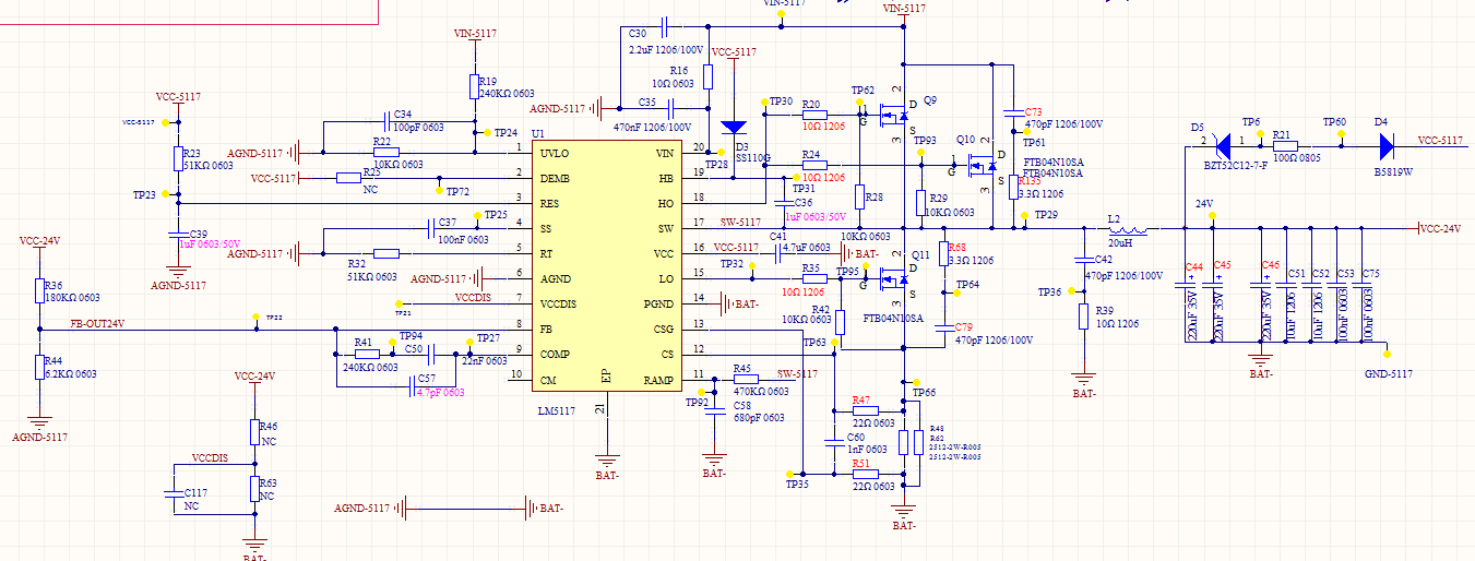
we used LM5117 as the buck controller, and  58V input and 24V output. The circuit diagram and test waveform are as follows:

channel 2 is 58Vin, and channel 1 is 24Vout. The input undervoltage point was set at 29V.

After the input voltage is reduced to the undervoltage point, the output voltage can only be 13V or 4V.

Please help to analyze the cause of this problem, and what needs to be modified?

  • Kane,

    How much output current are you designing for?

    Please share a full oscilloscope shot. I'm not sure where GND is and what the voltage scales are.

    Please also share the layout.

    -Sam

  • Hi Kane,

    I assume this scope shot is with Vin and Vout, please confirm. Also, please send the completed quickstart calculator Excel file for this design (you can find it in the product folder) - this allows us to review component selection.

    We should also review the layout (check that feedback resistors are close to the FB pin, CS filter components are close to CS and CSG pins, input caps close to FETs, etc.)

    Here are some comments on the schematic:

    1. 44ns filter time constant for current sense is somewhat high - try 20ns.
    2. Change LO gate resistor to 0 Ohms.
    3. Use 100nF boot cap.
    4. Only one component should be installed at the RES pin (either a cap to GND or a resistor to VCC).
    5. Remove external VCC connection for testing purposes (the power saving is not that much anyway given the 24V source).

    Regards,

    Tim

  • Hi TIm,

    thanks for your reply, i will try it ;

    and have any questions i will feedback to you!