Dear Sir,
The following is a description issue of TPS2121, whether there is a way to improve the voltage drop phenomenon caused by switching power channels, thank you!
IN1: VBATT_IN1 is in the range of 3.3V~4.2V.
INT2: VBAT_SYS is in the range of 3.3V~4.25V.
PR1: SYS_3V3 is always power on, BATT_ID_PRI is the battery ID pin of INT2 (VBAT_SYS), which is the signal of 10K resistor to ground.
BATT_ID_PRI and INT2 (VBAT_SYS) are in the same state, that is, INT2 is in place, that is, BATT_ID_PRI is in place, and INT2 is not in place, that is, BATT_ID_PRI is not in place.
OV1: AP_USB_VBUS is determined by whether or not USB is inserted. When USB is plugged in, the voltage is 2.7V; USB is not plugged in, the voltage is 0.
CP2: SYS_3V3 is always powered, CP2 voltage is 1.96V for a long time.
OV2: Ground
OUT1/OUT2: Four 22000nF capacitors are placed on the line
SS: Connect 1000nF capacitor
ILIM: Connect 22K resistor
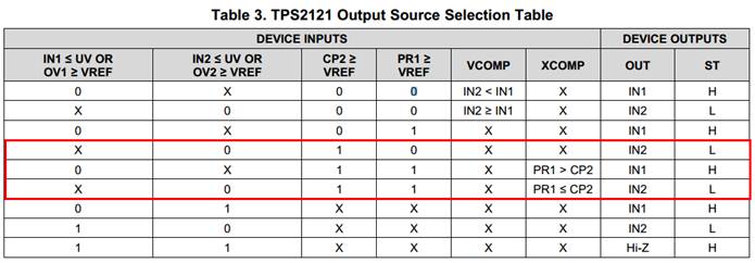
The logic in the red box below implements the active/standby switchover:
INT2 is connected to the main power, and INT1 is connected to the backup power.
1) When the main power is in place, PR1 is 0.42V, and the output is IN2.
2) When the main power is not in place, PR1 is 3.3V, and the output is IN1.
3) When USB is plugged in, OV1 is 2.7V and OV2 is 0V. At this time, the output is IN2 and will not switch to INT1.
The current phenomenon is:
When the main power is pulled out, when the main power is switched to the backup power, the output voltage is dropped.
When the direction of the main power is different, the battery ID and the main power supply INT2 may be disconnected from the connector.
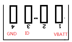
Main battery connector Pin definition and actual position map:
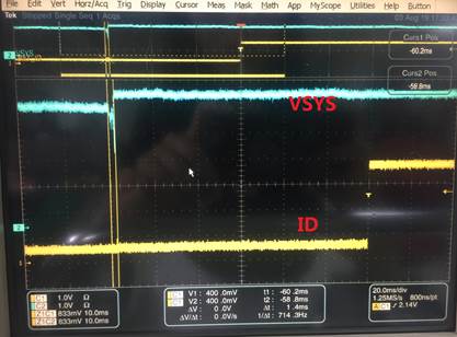
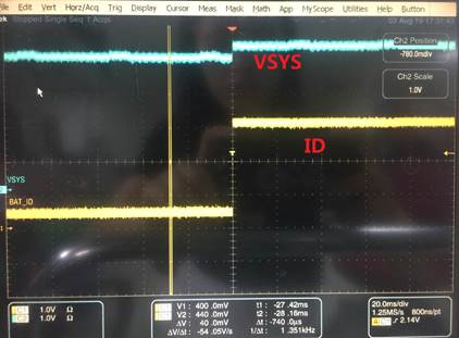
The following oscilloscope measurement waveform are shown:
yellow for the battery ID and blue for the TPS2121 output.
1) When the left side of the connector above is detached, the TPS2121 output has a drop voltage.
2)When the connector on the right side of the above figure is detached first.
There is no drop voltage.