This thread has been locked.

If you have a related question, please click the "Ask a related question" button in the top right corner. The newly created question will be automatically linked to this question.

TPS54336A: PH - GND short failure of TPS54336A

Part Number: TPS54336A

Hi!

My customer has had a problem that the PH and GND pins of the TPS54336A are shorted.

Problems have arisen when users are using them, and the number of defective products is increasing.

Below is the circuit configuration of my customers.

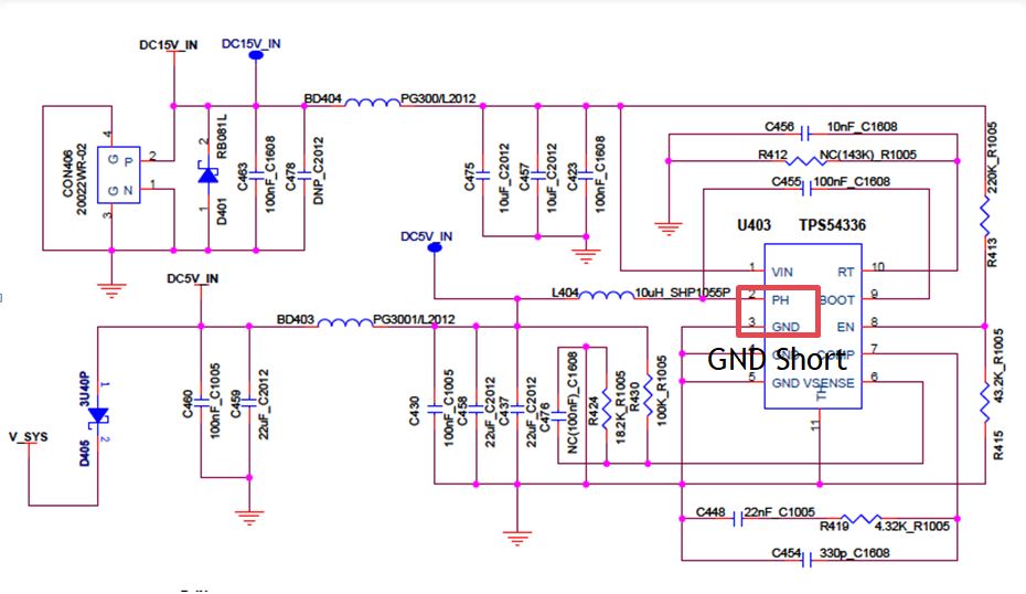
1. Is there a weak point that should be improved by design in the above circuit configuration?

2. In simulation(WEBENCH), 10uH, which is lower than 12 ~ 15uH, is used. The Isat value of the inductor used is also about 2.8A.Please refer to the datasheet of the used inductor.

(CKCH0704-10μH/M 

POWER_INDUCTOR_CKCH0704.pdf

Can you estimate the correlation between the use of the above inductor (lOW INDUCTANCE, lOW Isat) and the PH-GND shorting phenomenon?

3.I would also like to ask you about the compensation setting value and Phase Margin.

Thank you.

Best Regards

From Anthony.

  • Hi Anthony,

    1. Could you measure that if the PH-VIN is also short?

    2. Use a 10uH inductor instead of value from Webench is OK. It has nothing to do with the damage.

    3. For the compensation, you may try 10k+4.7nF, in parallel with 33pF.

    The damage issue might be related to the PCB layout. Could you post the layout here?

    Thanks!

    Regards,

    Hao

  • Thank you your reply.

    1. Could you measure that if the PH-VIN is also short?

    ==>it's not a short.

    2. Use a 10uH inductor instead of value from Webench is OK. It has nothing to do with the damage.

    ==>OK. I understand you, but the maximum value of the isat(Current when inductance is reduced by 20%) of the inductor used by my customer is 2.8A.

    If WEBENCH simulation is executed under the customer's input / output condition (Vin = 15V, Vout = 5V, Iout = 2.3A),
     At the start-up simulation , the inductor current is about 3A or more as shown below.

    3. For the compensation, you may try 10k+4.7nF, in parallel with 33pF.

    =>Ok, I'll check.

    The damage issue might be related to the PCB layout. Could you post the layout here?

    ==>Ok, I'll ask my customer.

    But the important thing is, We received a failure analysis report from TI and found the EIPD of the lowside FET position of the chip.

    Can you give me some advice about the failure modes that can cause this EIPD?

    Please check it.

    Thank you.

    Best Regards.

    From Anthony.

  • Hi Anthony,

    Yes, an inductor with inadequate saturation current may cause the current ran out. When current is higher than the saturation limit, the effective inductance will reduce rapidly. This may cause an over current event on the MOSFET.

    It's hard to say failure modes now... Most of these damage case are caused by over-voltage or over-current condition, which make the FET working out of its SOA(Safe-Operation-Area). Please post the layout and let's check if there is any thing not good. Thanks!

    Regards,

    Hao