This thread has been locked.

If you have a related question, please click the "Ask a related question" button in the top right corner. The newly created question will be automatically linked to this question.

TPS1H000-Q1: Reverse polarity protection

Part Number: TPS1H000-Q1

Hello everyone

I use TPS1H000-Q1 as a high switch during battery charge, to limit the current down to 500mA maximum. It works fine, but there are some conditions that damage the part. Here it is a schematic.

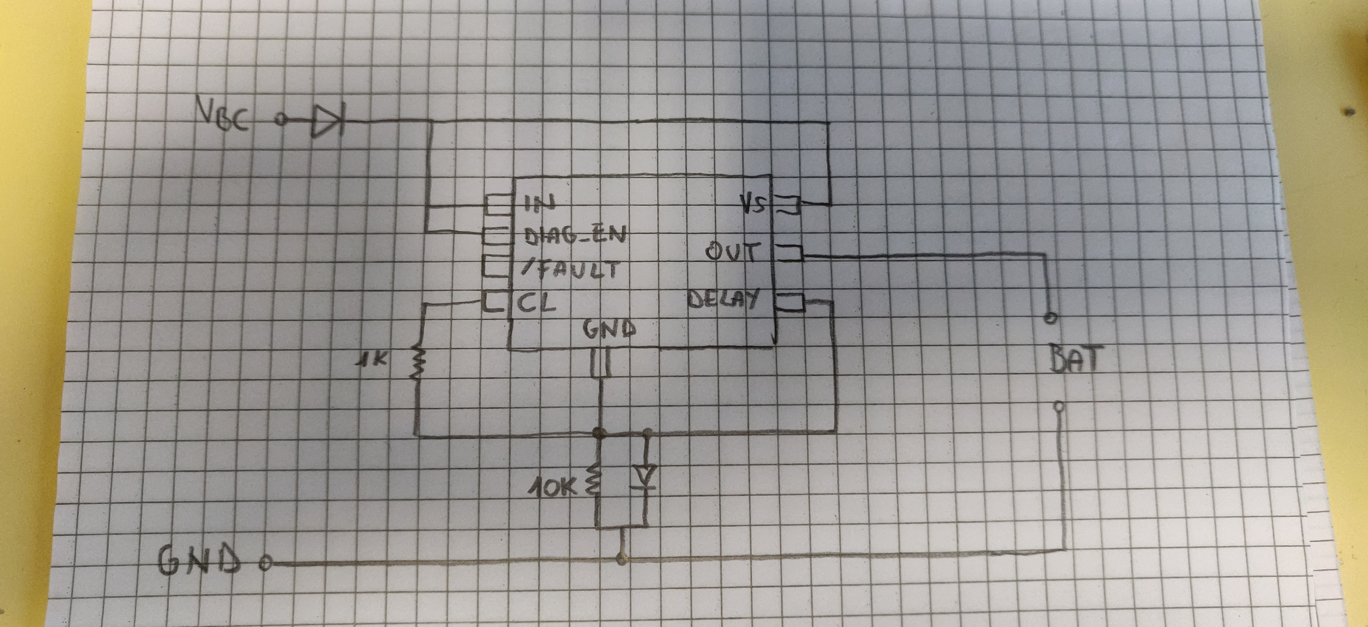
During normal operation battery is connected with positive terminal to pin "out" of TPPS1H000 and the negative to ground, and the charger is not connected. When the charger is connected correctly, current is limited to about 500mA and all works fine.

If we reverse polarity of the battery and the charger is not connected there's no problem and the part is protected.

If the battery is correctly connected, and we change polarity of the charger voltage, we wish to protect the system, but actually it doesn't happen because there's a problem and we damage the TPS1H000.

We would like to protect the system even if battery is in reverse polarity and we connect the charger, This is not the mail goal, but can be useful.

The case in which we have battery and charger in reverse polarity is not contemplate. 

So we need to find out why if we connect in a wrong way the charger, but battery is connected in a right way, the part will be damaged. Diode in VCB path should protect current flow because on the cathode we espect battery voltage (i.e. 24V), while on the anode we expect to have, for example, -27V respect GND (charger voltage reversed). Actually the high side switch, diode on the VCB path and diode on the Ground are damaged in this situation.

Does anybody can help us to find out the reason of the malfunction?

Roberto

  • Hi Roberto, 

    Thanks for reaching out on E2E!

    I am looking into your situation and will get back to you tomorrow. 

    Best Regards, 

    Elizabeth 

  • Hi Roberto,

    I would recommend putting current limiting resistors on diag_en and in pins.

    Could you clarify whether the source diode is failing or the ground diode is failing when the source is in reverse polarity?

    Best Regards,

    Elizabeth

  • Hi Elizabeth

    The ground diode die, and there's a short between Out pin and ground pin of the device.

    I made some little changes to the schematic, so there's no possibility to connect  a battery in a reversed mode. I use a switch, activated by source and battery at the same time, so if one of them is not in the correct polarity, or is not active, the switch stay open, and save the life of the TPS1H000-Q1.

    This is because I thought that if resistors on diag_en and in pins save the life fo the part during reverse battery, if we connect a positive source to source diode (e.g. battery charger) there's no way to save the source diode, because on the cathode we'll have -Vbatt, and on the other side +Vcharger.

    Roberto

  • Roberto,

    Sounds like you found a good solution!

    Can you confirm that your problem is solved by clicking the green "my question was resolved" button?

    Best Regards,

    Elizabeth