

Team,
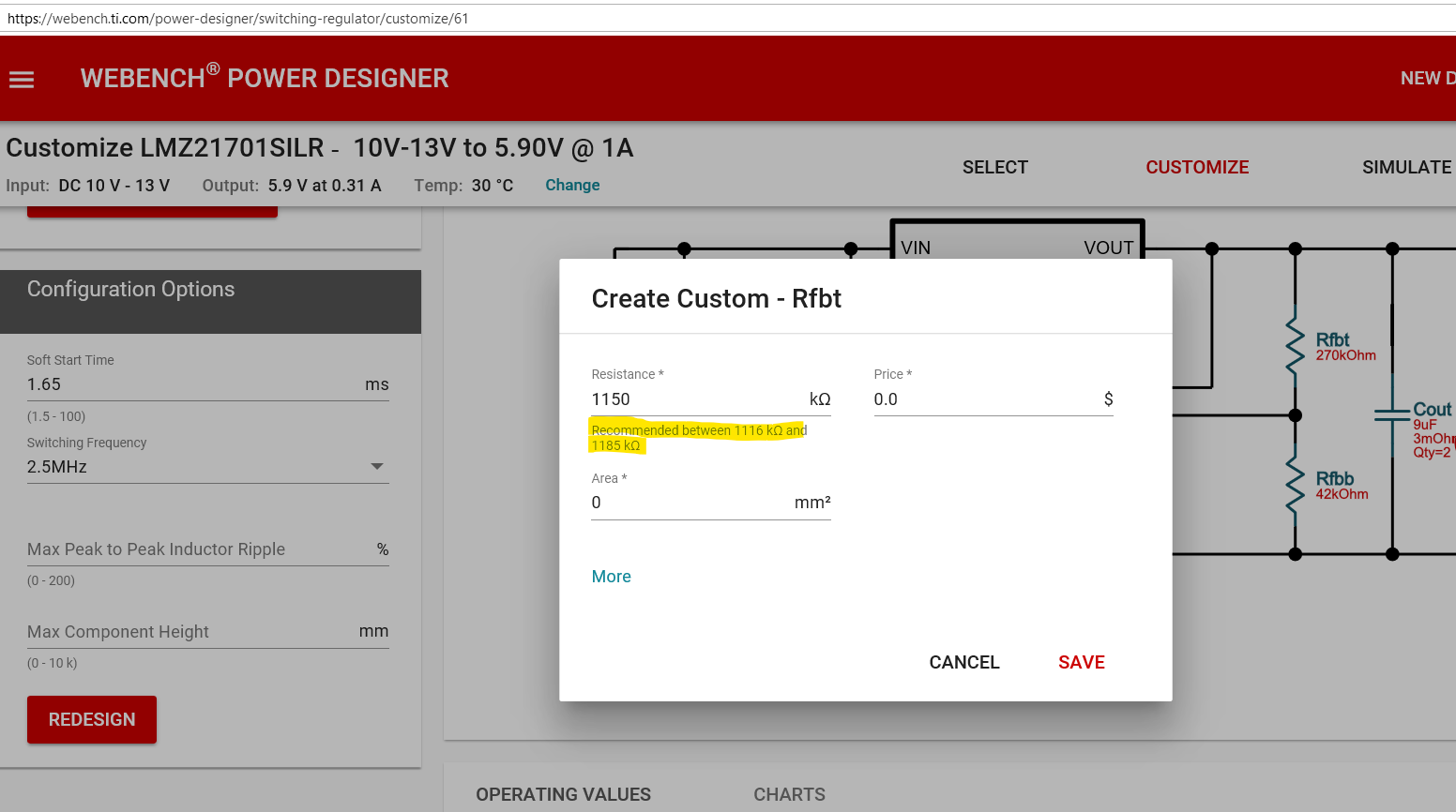
I was double checking myself for the LMZ21701 design on Webench. The datasheet for a 5.0V output has a 242k upper resistor. Webench recommends using a value 1.116-1.185Mohm. Why?
Team,
I was double checking myself for the LMZ21701 design on Webench. The datasheet for a 5.0V output has a 242k upper resistor. Webench recommends using a value 1.116-1.185Mohm. Why?
