NO OUTPUT SIGNAL PIN #14 & PIN #17.
Parameters:
Vin = 120VacRMS, fsw = 100KHz, Pout = 5000 watts, fline 47-63 Hertz, Vout = 390 V, Dmax = 90%, tss = 500mVDC
IC VOLTAGE READIN
Pin #1 = 3.28V, Pin #2 = 3.20V, Pin #3 560mv, Pin #4 = 1.52V, Pin #5 = 1.52V,
Pin #6 = 240mv, Pin #7 = 240mv, Pin #8 = 480mv, Pin #9 = 480mv, Pin #10 = 3.20V
Pin #11 = 240mv, Pin #12 = 320mv, Pin #13 = 5.76V, Pin #14 = 240mv, Pin #15 = 11.70V
Pin #16 = 240mv, Pin #17 = 240mv, Pin #18 = 1.52V, Pin #119 = 3.20V, pin #20 = 3.20V
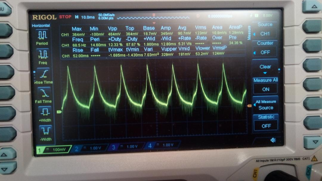
please review the scope waveform below.
Question #1: Is this the correct waveform for pin #3?
COMMENT: This waveform seems out of place compared to the other IC waveforms.
I have replaced the Vsense resistor with a trim pot so that I could vary the voltage from 1-volt to 3-volt. The Vvao always remain about the same voltage.
From what I understand is the Vvao should be higher than the Vsense.
Question #2) Should Vvao be higher than Vsense OR what should the voltage be?
Question #3) Looking at the Measure All Data, is there any reading that appears wrong/off?
Question #4) At what voltage should Vvao be greater than Vsense?
Question #5) With this information can you possible see why I do not get any output waveforms Pin 14 & 17?