This thread has been locked.

If you have a related question, please click the "Ask a related question" button in the top right corner. The newly created question will be automatically linked to this question.

UCC28950: UCC28950 Short Circuit Protection

Part Number: UCC28950

Hi Expert,

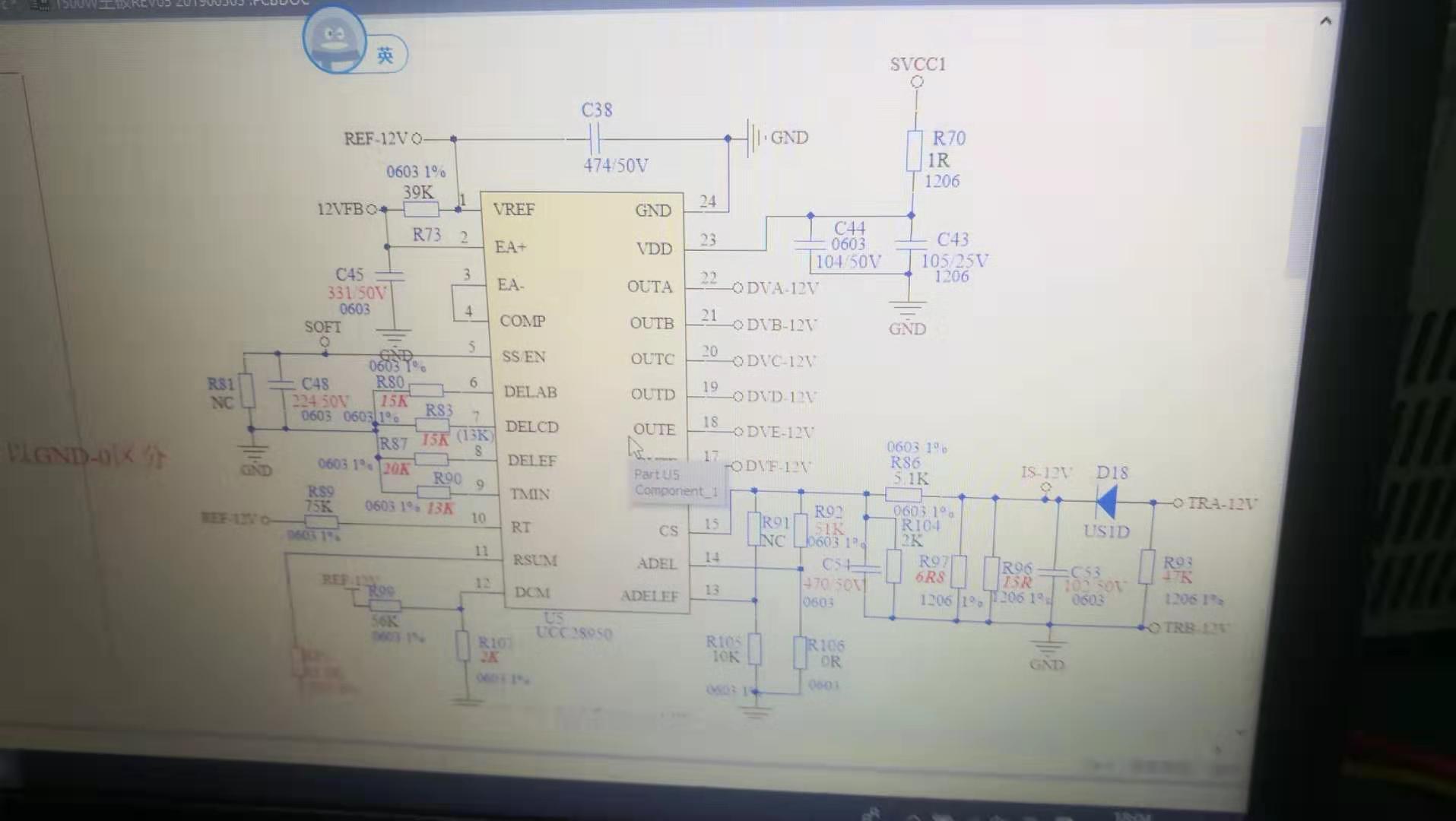
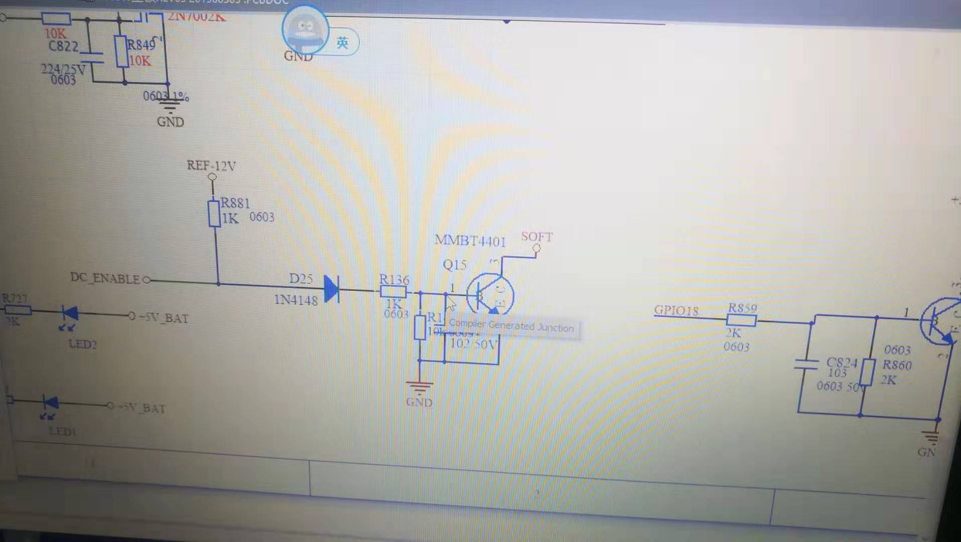
My customer is using UCC28950 now. When they set the input voltage to 200V, the circuit can trigger to protection properly, while when the input voltage is 400V, the protection function failed. They use the SS pin to protect the circuit. Could help check if there is something wrong on the design?

  • Hello Lenna

    Using the SS/EN pin in this way is usually the best way to provide short circuit protection but there are a few things to be careful of.

    The disable threshold for the SS/EN pin is nominally 500mV although it could be as low as 200mV so it is important that the collector of the transistor can pull down to this level quickly. The VCE saturation voltage curves for the 2N4401 indicate a VCE of < 100mV (Diodes Inc device Data Sheet - Fig 2) so this device should be ok.

    the second thing to check is the time between the DC_ENABLE signal going high and the final OUTx signal.

    The transistor has to discharge the SS capacitor as it turns on and the larger the capacitor the longer this process will take. It is possible to modify this by adding some resistance in series with the SS capacitor at the point X below. This will allow the transistor to pull SS/EN low more quickly - it will also slightly increase the SS time but the effect should be negligible. I'd suggest a 100 Ohm resistor for initial tests - this will limit the peak collector current to 5mA and the RC time constant is 220nF x 100R = 22us.

    I would also check that the time at which the DC-ENABLE signal is asserted is the same at 200Vin as at 400Vin - just in case they are different.

    Please let me know how you get on

    Regards

    Colin