This thread has been locked.

If you have a related question, please click the "Ask a related question" button in the top right corner. The newly created question will be automatically linked to this question.

LM3478: Drawing excessive current when loaded

Part Number: LM3478

Hi all

My problem is probably caused by a very silly issue, however at the moment I cannot see it. I hope someone out there can help. 

As a company we have previously used the LM3478 - i.e. it layed out on a previous PCB. 

We needed a new boost supply based on the same chip but with different input, output and current requirements. 

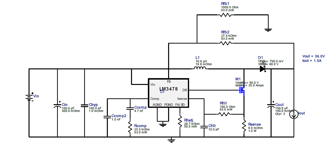
I designed this on with Webench. The resultant design had the same connection layout as what was implemented on the previous PCB. I therefore, as a first step implemented the changes in components to get the required output voltage and current. This worked. 

I then moved the design to a new PCB which I have fabricated. Component values are the same, but I have changed some of the components for space reasons. 

When I test the board unloaded, I can see the programmed voltage on the output. Probing the drive signal, I can see the programmed switching frequency. 

When I load the board with either 30 or 60 ohms, the bench power supply I am using current limits and the voltage collapses. The power supply is set to 17 V and the current limit at 3 A (the bench PSU's limit). The design is for an output of 37 V at up to 1 A with an input range between 8 ad 25 V. 

I know it is not much information to go on, but does anyone have any idea why when loaded the system starts to draw more current than expected. 

I will be unable to share the actual schematic or PCB layout, but I may be able to upload the Webench output, which in essence is the same. 

Any help would be appreciated. 

  • Hi Chithambaram,

    Thanks for considering the usage of the LM3478. Can you upload the webench output and comment on any changes between the schematic and the webench output?

    At a first glance, I wonder if this might be a power supply issue. Can you increase the input voltage of your power supply and see if the same condition occurs? 

    Thanks,

    Richard

  • Hi Richard,

    Thank you for the reply. 

    I attached the circuit generated from the Webench tool. 

    I have made the following changes

    • Cin is 2x 100uF Polymer Aluminium Electrolytic
    • Cbyp is not used/fitted
    • Cfilt is 10nF
    • Rfilt is 0R
    • L1 is 15uH
    • Rfb1 is 976R
    • Cout is 14x 33uF Polymer Tants 

    The same values were retrofitted into the previous board, which works.

    However as noted the PCB with the dedicated design does not.

    However one difference between the previous board and the dedicated design is that the previous board used standard electrolytic caps for the input and output rather than tants. 

  • Hi Richard

    Following on from my previous posting, I have tried increasing the input voltage of the power supply.

    The circuit has been designed for up to 25 V, so I increased the input from 16 V to 25 V. I have set the Bench Supply's limit to ~2 A. 

    When I connect a 60 ohm load (output is ~37 V, so the current should be about 0.61 A), the bench supply does not limit like previously, but the circuit does consume ~1 A (which I think is too much) and after about 30 seconds something starts to smell - I have not been able to identify what is smelling as yet. 

    I do not remember the above happening with the retrofitted test circuit. 

    I have also changed the inductor to 10 uH and change Rfilt to 100 ohm. Still no luck.

    I know that actual component layout and track routing can affect power supplies, with some layouts better than others, however can a bad layout and tracking cause so much destruction as to stop the whole thing working?

    Thanks

    Chithambaram