This thread has been locked.

If you have a related question, please click the "Ask a related question" button in the top right corner. The newly created question will be automatically linked to this question.

TPS62745: help clearing up 55mV output ripple

Part Number: TPS62745

Hello,

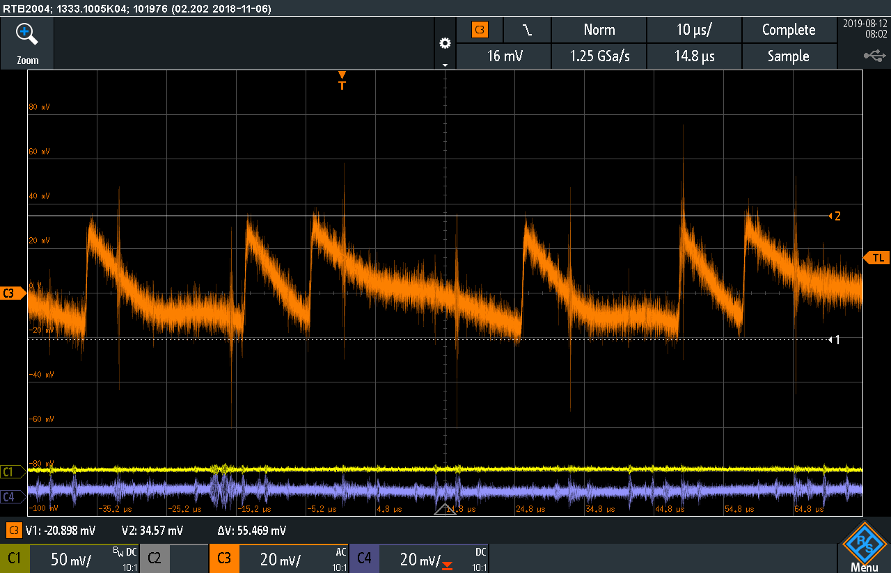
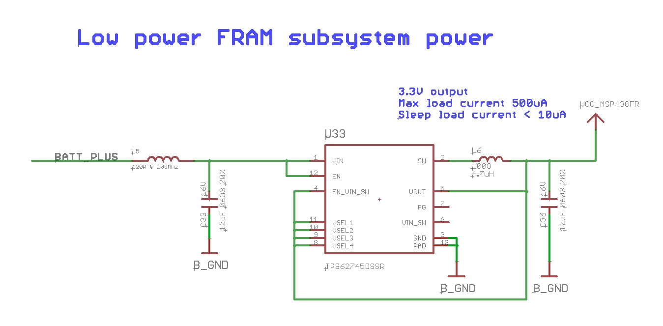
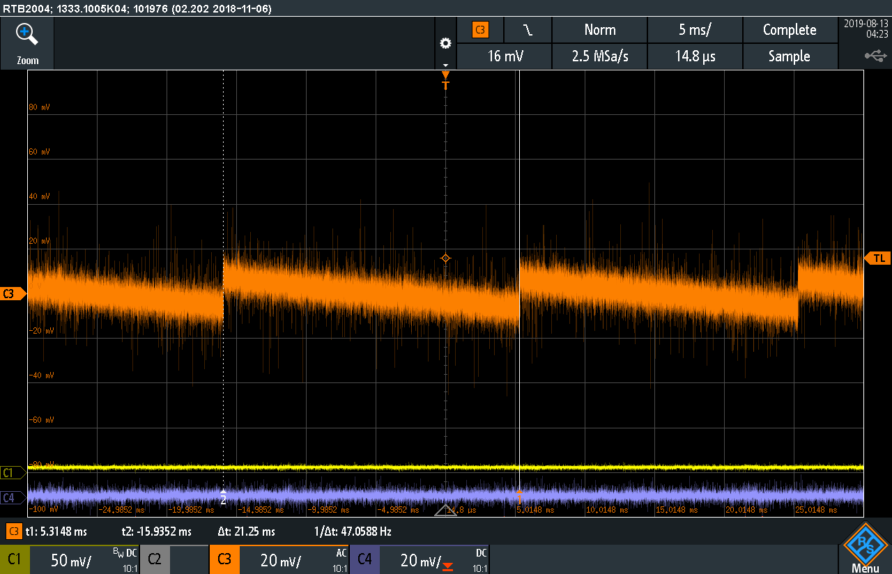
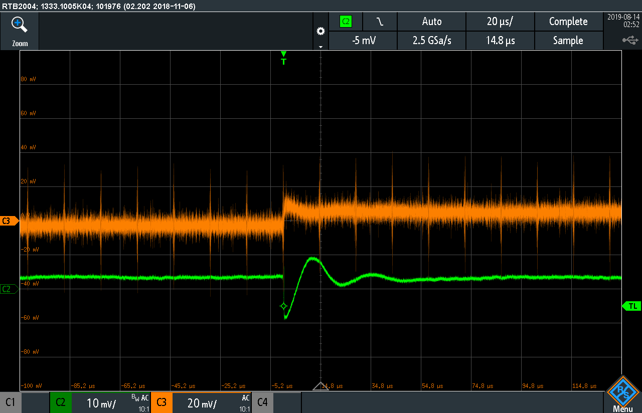
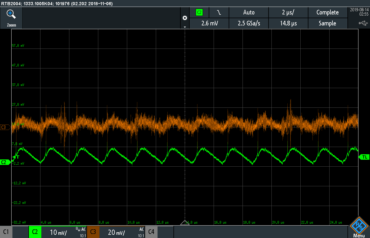
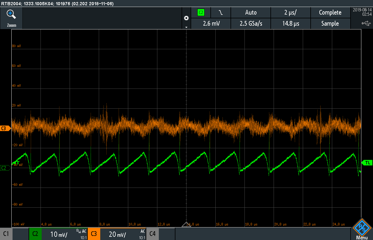
I am trying to design the tps62745 into a product and this supply (3.3V output version) will be supplying anywhere from 10mA to 10uA loads.  I'm not sure exactly where in that window I will be yet.  Most likely less than 1mA.  This seemed like a great simple solution, but now that I have a test board with one of these up and running it is very noisy.  I've attached a screenshot showing the output noise in orange (scope trace).  This power supply is powering an op-amp and although it isn't extremely high precision it needs to be cleaner than what is shown in the scope capture.  This power supply is shown in the second screenshot attached. 

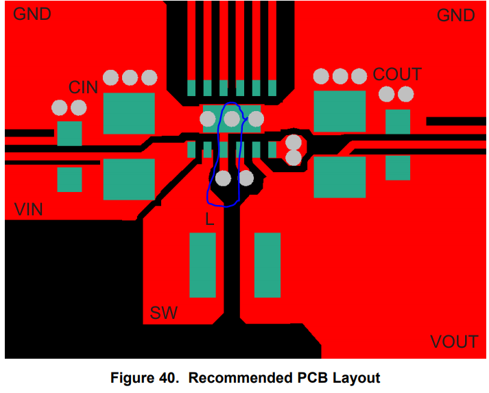
I believe this is connected just as it is shown in the data sheet example.  There is no active circuitry on this board aside from this supply.  The load is a BK precision 8601 active load.  The input voltage is 8.2 volts.  

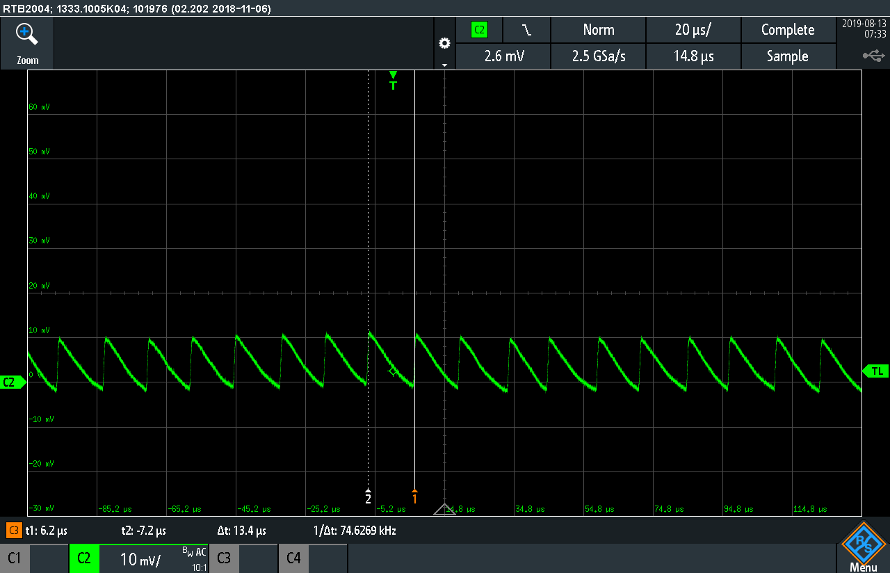
Ch3 in scope capture = output of TPS supply with 10mA load for testing.  I noticed that as I increase the load the switching speeds up and the peaks of this noise (sawtooth looking waveform) shrinks.

Is this the expected behavior of this supply?  Should the inductor be increased to help smooth this out?

  • Hello,
    Can you please also share the layout? Was the load constant during this test? Can you make a test adding more output cap? Usually, capacitor (0603) can have a significant dc bias, so maybe you don' t have 10uF at the output.

  • Hi Alfonso,

    Thank you for the reply!  The load was constant.  Below are two pictures with two parallel 10uF  16V 0603 capacitors on the output.  The below screenshots show the output voltage with a constant 10mA load from  a BK precision active load as described above.  The sawtooth waveform is still there.  The layout is also shown.  The frequency of the sawtooth pattern is shown by the cursers.

    It seems the magnitude did come down some.

    Layout

  • Here is the output voltage with 2x 4.7uH inductors in series.  The rest of the circuit is the same as described in the above post.  The magnitude of the output noise(ripple/sawtooth) seems to come down with increased L or Cout or both.

  • Hello,
    from the new scope plots (C3) it seems that the device is working fine. The dc bias of the output cap affected the stability of the converter; in fact, your first scope plots showed a non-periodic waveform. The spikes maybe are coming from other circuitry and are not due to the converter itself. I attached our recommended layout (comment highlighted in blue) because I noticed that perhaps the connection between the ground pin and the thermal pad is missing in your layout. Also, add more vias to the thermal pad would be good.

  • I will look at the input in more detail.  There is nothing else on the pcb aside from this regulator so it can only be due to the tps supply or my bench power supply providing 8.2v input power.  I will look more into this tonight.

  • So that level of output ripple ~12mVpp is typical for this part?

  • So adding 20uF caps to input and output and using two 4.7uH inductors in series seems to quiet down the supply quite a bit.

    Here is a screenshot with no load with this configuration.  Ch3 (orange) = output Ch2 (green) = input

    Here is a screenshot with a 50mA load with this configuration.  Ch3 (orange) = output Ch2 (green) = output (both channels show output but ch2 is using low inductance ground lead)

    Here is a screenshot with a 50mA load with this configuration.  Ch3 (orange) = output Ch2 (green) = input

    Is there any risk in stability or performance if I increase the inductor to smooth this out? 

  • Hello,
    In figure 18 of the D/S, you can find the value of the output ripple function of the output current. Which technique do you use to measure the output voltage ripple and the inductor current? What about my feedback on your layout? About the LC filter, you can have a look into section 9.2.2.2 of the D/S to not have a stability problem. Do you have specific requirements in terms of ripple for your application?

  • Hello,

    I am going to close this post due to inactivity. If you need further support, please re-open it and I will be glad to support you.