This thread has been locked.

If you have a related question, please click the "Ask a related question" button in the top right corner. The newly created question will be automatically linked to this question.

TPS63000: Device consumes a lot of power and the temperature is high without load

Part Number: TPS63000
Other Parts Discussed in Thread: TPS63020

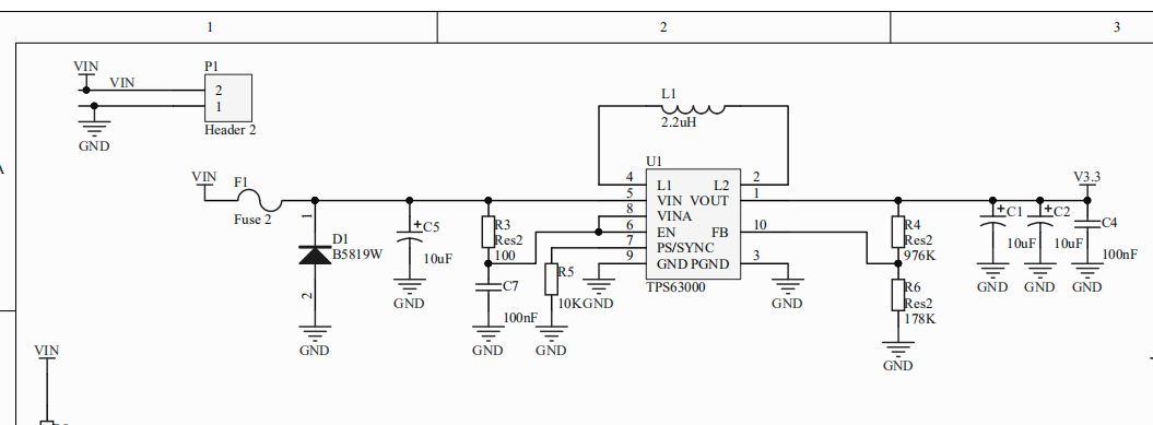
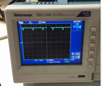
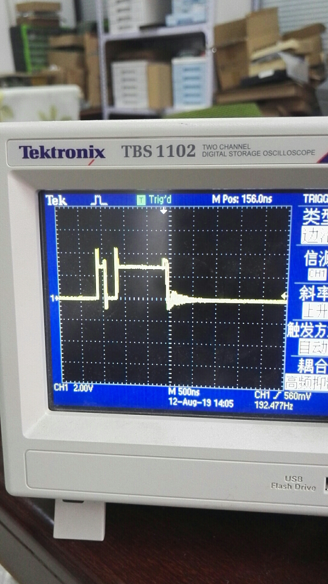
Equipment 3.6V battery power supply, found that the battery quickly lost power, board MCU, TPS63000, wireless module several chips, test wireless module working current 100mA, not working under 5mA, TPS63000 heating, wireless module not working, board power consumption reached hundreds of milliamperes, the following figure 1 is a circuit diagram, Vout measurement found that there is a sharp point. Peak, Figure 2 below is Vout, Figure 3 is the waveform at the measured inductance.

  • Hi Zhang,

    The schematic looks fine. Could you please post the PCB layout? Just the part around the TPS63020 is enough.

    I see that the output voltage drops every second, I assume that is when the load turns on? Please make sure that the current rating for your inductor is appropriately selected. And also check if the thermal pad is soldered and connected to the ground.

    Best regards,
    Milos

  • One MCU, one wireless module and one TPS63000 are on board. The load is removed from the board, and only one TPS63000 chip is left. Measurements show that the power consumption is 230 mA, and TPS63000 is damaged quickly. The peak of 1S is caused by periodic wake-up during MCU sleep. The following picture is PCB. We measure the power consumption of overloaded sleep. 200uA, 30mA when MCU wakes up, 100mA when wireless module works. Please help us see what causes TPS63000 damage.

  • Hi Zhang,

    Is this PCB for the same circuit as the one on the schematic? Because some part designators does not match. For the circuit from the PCB above, can you check the following:

    1. Did you make sure that the thermal pad and both PGN and GND pins of the TPS63000 are soldered to the board?
    2. If C1 is electrolytic capacitor, try to replace it with a ceramic capacitor, or just add a 10 μF ceramic capacitor between C1 and VIN.
    3. Please send us scope plots of VIN, VOUT, L1, L2 voltages and input current during startup.

    Best regards,
    Milos

  • Hi Zhang,

    We haven’t heard back so we're assuming this resolves your issue. If not, just post a reply below, or create a new thread if the thread has locked due to time-out.

    Thanks and regards,
    Milos