This thread has been locked.

If you have a related question, please click the "Ask a related question" button in the top right corner. The newly created question will be automatically linked to this question.

TPS50601-SP: Shutdown during current inrush

Part Number: TPS50601-SP

Hi Daniel, recently we've noticed an issue where our 1.8V regulator is entering a shutdown condition and restarting after a load on the 1.8V bus is enabled and the resulting inrush current causes the 1.8V supply to fall below regulation. The inrush lasts for about 80us and we've estimated that the peak current could be 8-9A (ignoring current ripple in the inductor) based on a simple Cdv/dt calculation. From the datasheet, this pulse could be exceeding the current limit for both the high and low side switches. The regulator is nominally switching at 500KHz, so I could expect up to 40 switching cycles to be operating in a current limited fashion. This pulse causes the 1.8V to immediately dip by about 10%. Then one of two things happen, either the regulator simply recovers back to 1.8V or it shuts off and restarts. My reading of the datasheet suggests that the only thing that would lead to this kind of shutdown is tripping the UVLO, the enable threshold or a thermal shutdown.  Both the enable and Vin are at 3.3V. Thermal shutdown strikes me as unlikely given the short duration (80us).  Is there anything outside of these conditions that can trigger a shutdown?

  • Hey John,

    What is the soft start you are using for the TPS50601-SP?

    Sometimes using low values for this can cause high inrush current.

    I would be interesting of seeing this 10% dip at start up if you have waveforms.

    Thanks,

    Daniel

  • Hi Daniel,

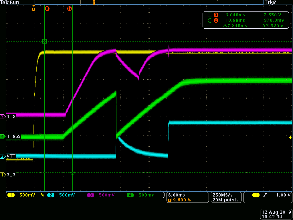
    We're using a 0.027uF cap for the soft start. However, I should clarify that it is not the initial inrush during startup that is creating the problem. The regulator's pwrgd enables a linear VTT regulator downstream. When that load kicks in, it's inrush is what is pulling down the 1.8V regulator. This also causes the pwrgd line to drop which disables the linear VTT regulator. The 1.8V appears to then enter a shutdown and then tries to come back up. In some cases this can lead to a limit cycle of starts and stops before the 1.8V finally enters into regulation.  We've observed that this limit cycle can be sensitive to the choice in compensation components and can persist for many cycles, .e.g >10 in some cases.  We have been able to prevent the limit cycle from occurring by modifying how the VTT regulator is enabled, thereby greatly reducing it's inrush current. However, in trying to get to root cause, I'm being asked to explain the initial mechanism that leads to this limit cycle occurring.The concern is that prior to the VTT modification, the nominal compensation values chosen exacerbated this issue. However, these values clearly provide better dynamics in a small signal sense as we've observed less overshoot during load changes. My primary goal is to understand what mechanisms could lead to this behavior to ensure we now have a robust design.

    Thanks,

    John

  • Hey John,

    It would be more useful to see the inrush current as a load step on the TPS50601-SP.

    When thinking of it like this it becomes easier to understand why this is happening.

    In this case, this means that the main contributors to the droop will the the compensation and output capacitance.

    Increasing the crossover frequency/output capacitance will help immensely.

    Our PGOOD will drop when the output is outside of regulation.

    This can be for many different reasons, but here its because the transient caused the device output to drop.

    Thanks,

    Daniel

  • Hi Daniel,

    I understand why this load transient causes the output to droop and lose regulation. That's not really the question I'm trying to answer. I don't understand why the regulator is entering shutdown, you can clearly see the soft start cap being discharged before the regulator comes out of shutdown as described in the datasheet. The datasheet seems to only cite 3 reasons for entering a shutdown. 1.) pulling the enable below 1.032V. 2.) When the UVLO is triggered. 3.) Thermal Shutdown. We've ruled out 1 and 2 through direct measurement. 3 seems rather unlikely given the duration (80us) of the load current, plus locally cooling the part makes the problem worse (increases the length of the limit cycle).  We've also seen this behavior on multiple parts so it's likely not a part issue. Am I missing another intentional protection feature for entering shutdown?

    Thanks,

    John

  • Hey John,

    The only three things that would shut the device off in this mode would be the current limit, thermal shutdown, or enable pin.

    My guess if you were correct with the assumption it was the current limits.

    The current limit of the device can change over temperature as well which would explain why it got "worse" at colder temperatures.

    Thanks,

    Daniel

  • Hey Daniel,

    I thought that the current limit was used to determine cycle-by-cycle limiting as described in section 8.3.17 not for initiating a shutdown? There's no mention of this in the datasheet. If what you say is correct, this would definitely explain what I'm seeing. However, Fig 8 shows that the current limit (at least for the high side FET) goes up at lower temperatures. So it would trip less, which is not what we observed. It also doesn't explain why the limit cycle phenomena is so sensitive to the value of the compensation lead resistor.  Can you please double check that the current limit circuitry can indeed cause a shutdown? 

    Thanks,

    John

  • Hey John,

    There are quite a few things that would be considered current limits in the device.

    The section you are talking about is talking about the cycle by cycle current limiting done by comparing  COMP and the current.

    There is another over current protection that happens when COMP reaches 2 Vs.

    This current limit will shutdown the device and cause a restart.

    Thanks,

    Daniel

  • Hey Daniel,]

    That's exactly the sort of information I was looking for, thank you! The information regarding this particular current protection engaging if the COMP pin voltage exceeds 2V is not covered in the datasheet. If it is please let me know where it is located. It goes a long way to explaining everything we've observed. Thanks again.

    -John

  • Hey John,

    Its certainly not explained the the application section, but it is actually noted in the electrical characteristics.

    The 3 current limits are noted there.

    Thanks,

    Daniel

  • Hi Daniel,

    I was fairly sure those thresholds referred to the cycle-by-cycle current limiting. The 2V limit on the COMP for overcurrent shutdown does not appear to be...

    Thanks,

    John

  • Hey John,

    The 2 V on COMP is how the high side one is set.

    I think your right that I am getting a little confused.

    I was thinking of the COMP voltage limiting the current as the error voltage is compared to the current rather than the max COMP voltage saturating and limiting the current.

    In any case, you would be able to check by measuring the COMP voltage if you are hitting the high side current limit.

    Thanks,

    Daniel