This thread has been locked.

If you have a related question, please click the "Ask a related question" button in the top right corner. The newly created question will be automatically linked to this question.

BQ24195L: Boost Mode / USB OTG - not kicking in

Part Number: BQ24195L
Other Parts Discussed in Thread: BQ24195

Hi,

I'm using the Arduino MKR WiFi 1010, which uses a BQ24195L.

I've written 10 to REG01[5:4] and set the OTG pin HIGH, as described in the datasheet. I can read REG01 back and see it's set correctly. However, PMID does not go to 5.1V.

How can I diagnose this issue?

I wondered if I had the same issue as this person -

e2e.ti.com/.../398042

Any pointers greatly appreciated.

  • Kieren,

    The conditions for running in boost mode are:

    1. BAT above BATLOWV threshold. Is your battery charged enough and at voltage greater than the BATLOWV threshold set by REG04[1]?

    2. VBUS is less than BAT+VSLEEP. The device cannot be in sleep mode. 

    3. Boost mode must be enabled. You already did this

    4.220 ms must pass to allow for boost mode to activate

    Once these four conditions are met you should see REG08[7:6] show 11 indicating the device is in boost mode. If you do not see this, then one of the above conditions is not being met.

    Thanks,

    Ricardo

  • Thanks Ricardo. I believe all of those conditions are met:

    Bat exceeds the configured minimum (its close to 4v)

    VBUS is 0 (cable is disconnected)

    Ive waited many seconds

    Is there nothing else I can try?

  • Is there another hidden requirement - do D+ and D- need to be connected?

    Looking at 8.3.1.3.4 in the datasheet, the input current limit detection process depends on them not being floating. If they're disconnected would it make a difference here?

  • Kieren,

    D+/D- is unrelated to the boost operation as it only sets the input current limit during buck operation. Would be possible for you to recreate this issue on our EVM?

    Thanks,

    Ricardo

  • Hello,


    I have not heard back from you in a while. Please let us know if you have any further questions, otherwise I will be closing this thread.


    Thanks,

    Ricardo

  • Hello Recardo,

    can you tell me how do i use the registers of BQ24195 using i2c ?

    i am using esp32 on arduino ide.

    i want to set the registers using i2c and get the information from them.

    i hv connected i2c pins to esp32 .

    how do i set specific bit of any registers??

    please guide me.

    Thank you

  • Nishi,

    In the future please make any new questions a separate thread, so others in the future can find the answer easily.

    Here is a link to the BMS GitHub repository. Use the source files provided there to communicate between your microcontroller and bq24195. Please ensure you have appropriate pull-up resistors on your I2C bus as shown in section 9.2 of the datasheet.

    Thanks,

    Ricardo

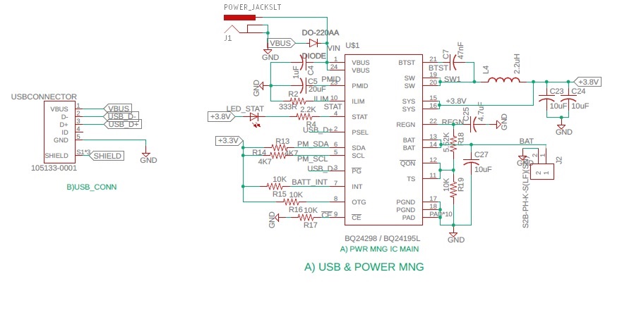
  • This is the schematic what i have used

  • Hello Ricardo,

    Wire.beginTransmission(BQ24195L_Slave_Address);
    Wire.write(BQ_REG[4]);
    Wire.write(0x59);
    Wire.endTransmission();

    Wire.beginTransmission(BQ24195L_Slave_Address);
    Wire.requestFrom(BQ24195L_Slave_Address, 100);
    Wire.endTransmission();

    this solves my issue i get required voltage at STAT i.e 3.8v

    using this value Wire.write(0x59)

    Thank you,

    Nishikant

  • Nishikant,

    Thank you for the update. Let me know if there is anything else you need from me, otherwise please click the "this resolved my issue button."

    Best Regards,

    Ricardo