This thread has been locked.

If you have a related question, please click the "Ask a related question" button in the top right corner. The newly created question will be automatically linked to this question.

LM5145: LM5145 ripple terrible

Part Number: LM5145
Other Parts Discussed in Thread: LM5146-Q1

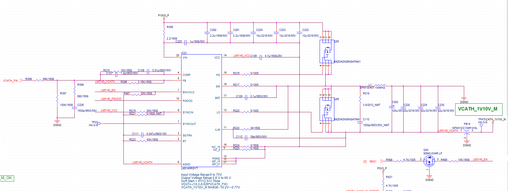
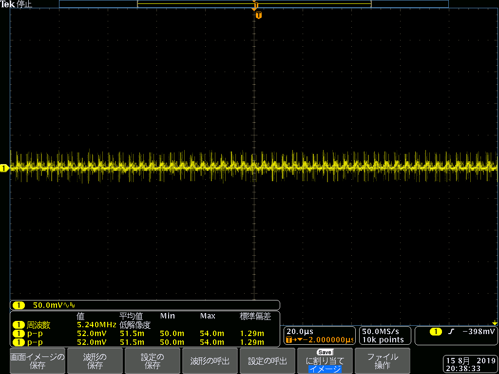
I would like to ask that the LM5145 to do a positive 15V voltage conversion into output voltage negative 5.5V voltage( a DAC to adjust ), at the current 1A output, the output waveform is terrible, may I ask what is wrong.


Adding Attachments:photos of schematic and output waveforms, layout screenshot

  • Hi Xingquan,

    Please send a completed LM5145 quickstart file for this design.

    Also, please refer to the PCB layout guidelines in the LM5145 datasheet. The input caps in your layout are too far away from the FETs and route the switched current under the controller. The layout of the LM5146-Q1 EVM has a similar FET arrangement - please refer to that layout for recommended input cap placement.

    Regards,

    Tim

  • Hi Tim

    Thank you for your reply.

    What's the  LM5145 quickstart file.I am not sure about this document.

    In addition, in addition to the layout may cause output problems, do I have other ways to improve it?

  • Hi Xingquan,

    You can download the quickstart calculator from the product folder, see here: http://www.ti.com/product/LM5145/toolssoftware#devtools

    Note that you can measure the SW node voltage to check that the converter is stable. If the main issue is noise and spikes on the output voltage, then I recommend connecting a small 10-47nF cap near the FETs from VIN to GND, i.e. from drain of high-side FET to source of low-side FET. This reduces the switching loop parasitic inductance and thus the SW voltage ringing (which can propagate to the output via the parasitic capacitance of the inductor).

    Also, you can add an output capacitor after the ferrite bead to improve the high-frequency attenuation of that filter stage.

    Regards,

    Tim