This thread has been locked.

If you have a related question, please click the "Ask a related question" button in the top right corner. The newly created question will be automatically linked to this question.

BQ76940:Parallel connection Bq76940

Part Number: BQ76940
Other Parts Discussed in Thread: BQ76930, BQ76200

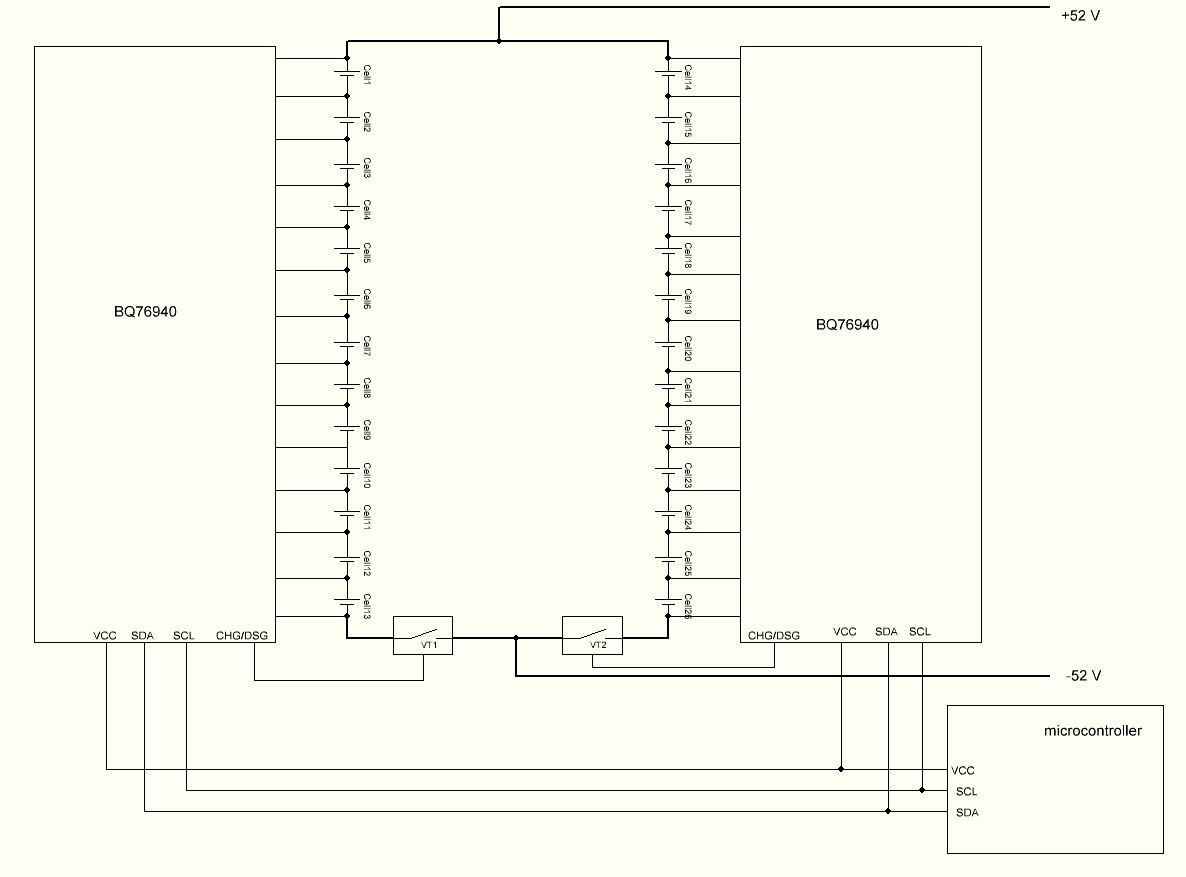
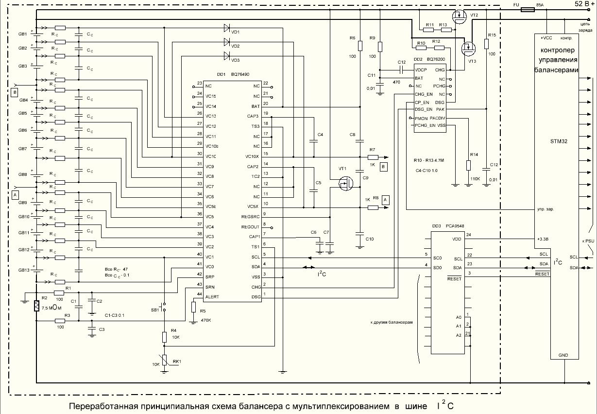
Good afternoon! Tell us if this parallel connection of the BQ76940 is possible, with MOSFET at the bottom of the circuit. I2C is enabled in parallel. Power is switched on in parallel to increase power.

  • Hi Dimitry,

    I'm confused - I haven't seen something like this before. Is there a reason you are not connecting the cells in a 13S2P configuration and are instead connecting them only at the end-points? Normally, I would expect each pair of cells to be connected together so that the voltage on each cell pair is the same with the benefit of additional capacity. While this configuration seems possible, it also seems like there are a number of scenarios that could be difficult to predict. 

    The BQ76940 is available with different part numbers that have different I2C addresses. The ALERT pin from each device notifies that microcontroller that a new measurement is available or that a fault has occurred. The microcontroller would need to monitor this pin for each device and respond. 

    Best regards,

    Matt

  • Hello, Matt.
    I wanted to know if the circuit would work if I connected the keys (transistors) to the bottom of the circuit, and I would connect the I2C bus to one microcontroller port.
    With the transistors connected in this way, each circuit is at 50 V. As I understand it, the I2C bus must be connected inside the chip to the signal ground. The keys, in my case, will be switched toto take turns studying. Will there be a voltage drop between the bq766940 circuits during this connection? One is connected (key is closed) to the ground, the other is disconnected from the ground (key is open).

  • Hi Dimitry,

    I'm still having trouble understanding exactly what you are trying to do, but ground should never be removed from the device. The device can be disconnected from PACK-. If the microcontroller is outside of the battery pack, it can use PACK- as a ground reference. If the transistors open, then BATT- (ground of the BMS system) disconnects from PACK- and you will lose communication with the microcontroller. If the microcontroller is inside the Pack, it should use BATT- for ground. In this case, you should use different part numbers (bq7694002 and BQ7694006) that have different I2C addresses or you can use an MCU with 2 I2C ports. 

    One TI reference design that uses one I2C port to reference 2 different BQ76930 devices might be helpful: http://www.ti.com/tool/TIDA-01093

    Regards,

    Matt

  • Hello, Matt.
    In my case, the 13sp2 structure is used. But each parallel branch uses its own bq76940. A set of cells connected in series will be charged one by one. This means that one transistor is open, the other is closed. As I understand from the structural scheme of bq76940, the I2C bus inside the chip itself is connected to the common ground of the chip bq76940. I want to know the answers to 3 questions.
    1. Is the I2C bus inside the chip itself connected to the common ground?
    2. As I said in the previous post, wouldn't there be a voltage drop between the bq76940 chips connected in parallel when one key is closed and the other is open? In the diagram above, U is the voltage drop between the bq76940 chips.
    3. Is it possible to connect 2 or more I2C buses per microcontroller (I use a separate chip bq76940, for each parallel branch)? If not, why not?
    Please give a specific answer for each item.

    From my point of view, I will explain why there may be a voltage drop between the chips bq766940. When one transistor is closed, this bq76940 is connected to earth. At this point, the other transistor is open, this bq76940 is connected to +50 V (in my case). I am worried that if the I2C bus is connected in parallel, there may be a voltage drop between these circuits.
    Regards, Dmitry.

  • Hi Dimitry,

    1. Is the I2C bus inside the chip itself connected to the common ground? Yes
    2. As I said in the previous post, wouldn't there be a voltage drop between the bq76940 chips connected in parallel when one key is closed and the other is open? In the diagram above, U is the voltage drop between the bq76940 chips.Both BQ76940 chips VSS pin should connect to the bottom of the lowest cell. Since you are proposing separating the two strings completely, then yes there can be a voltage drop.
    3. Is it possible to connect 2 or more I2C buses per microcontroller (I use a separate chip bq76940, for each parallel branch)? If not, why not?
    Please give a specific answer for each item. It is possible to connect two I2C buses together. However, you must find a way to specify which BQ76940 you want to communicate with since both may have the same I2C address. You could do this by uses two different I2C ports on the microcontroller, you can select two different BQ76940 part numbers with different I2C addresses (see table at beginning of datasheet), or you can add circuitry to control which device receives the communication.

    Best regards,

    Matt

  • Hello,Matt.
    Thank you for answering my questions. I have a few more questions.
    A few questions about using chip BQ76940 in combination with BQ76200. We are planning to use BQ76940 in rechargeable battery 13S8P with individual balancing for each of the parallel group. Data sheet doesn’t mention possibly of such use.
    1. Is it possible to monitor battery status from the parallel ports (8 balancers bq76940) using one controller? Is it only possible with the switches in upper position? Maybe you have different solution? Using an I2C Multiplexer?
    2. How to deal with two unused connectors for the upper batteries?
    3. Could we ignore signals from “alert” contact and keep them floating
    4. We are planning to use dynamic charging for the batteries with low current. Is it possible to use recommended BQ76200 with the controller for switching of the sections keeping control of individual balancers?
    Thank you! Regards Dmitry.

  • Dmitry,

    This use case is unusual. In most applications, one bq76940 is used to monitor both strings together, but this would require a connection between each pair of cells. This greatly simplifies cell balancing and protection since parallel cells will always be at the same voltage.

    1. Is it possible to monitor battery status from the parallel ports (8 balancers bq76940) using one controller? Is it only possible with the switches in upper position? Maybe you have different solution? Using an I2C Multiplexer? This may be possible, but you will need to come up with a way to control communication since all of the bq76940 devices will have the same I2C address.
    2. How to deal with two unused connectors for the upper batteries? See the section on Configuring Alternative Cell Counts in the datasheet.
    3. Could we ignore signals from “alert” contact and keep them floating  No, we do not recommend this. The ALERT pin reports to the MCU when a new measurement is ready and when a protection fault has occurred. It should be monitored by the MCU.
    4. We are planning to use dynamic charging for the batteries with low current. Is it possible to use recommended BQ76200 with the controller for switching of the sections keeping control of individual balancers? I'm not clear what you are asking. The BQ76200 is a high-side FET driver. I think you may need to draw a schematic of what you are trying to do to help make it clear.

    Best regards,

    Matt

  • Dmitry,

    The PCHG_EN pin controls the PCHG output of the BQ76200. You don't have the PCHG pin connected to anything in this picture.

    Matt

  • Hello Matt.
    Wrong drawing of the wiring diagram for the last time. Here is the circuit diagram I'm going to use. The question is the same. Is it possible to use recommended BQ76200 with the controller for switching of the sections keeping control of individual balancers?
    By switching the transistor using the CP_EN output?
    Regards, Dmitry

  • Hi Dmitry,

    CP_EN can be used to control the FETs. However, there are a couple of things to keep in mind regarding this:

    - The charge pump is enabled if CP_EN is high or if CHG_EN or DSG_EN are high. Even if CP_EN is held low, the charge pump will turn on if one of the FETs is enabled.

    - The charge pump turn-on time is slow, ~100ms according to the datasheet. It is generally recommended that CP_EN be set high once at system startup for most application. I understand your application is unique.

  • Hello Matt?
    I want to measure the current with a current sensor. The current sensor is in a +52 V power bus rupture. The signal from the current sensor will be scaled to a voltage range of +-200mV. I understand that the measurement accuracy will be reduced. I want to know if a 16-bit ADC can measure current under such conditions.
    Regards Dmitry.

  • Hi Dmitry,

    Some other users have implemented a hall sensor into their design successfully. The accuracy will vary over temperature according to the ACS711 datasheet, but it might be okay for your application. 

    Some important things to consider:

    • The input voltage of SRP and SRN should stay within the datasheet input range (+/-10mV for SRP, +/-200mV for SRN). 
    • Make sure to review the Design Example walk-through in section 11.2.1 of the datasheet. In this process you need to consider the current detection levels for over-current protection and short-circuit protection.

    Best regards,

    Matt

  • Thank you, Matt.