This thread has been locked.

If you have a related question, please click the "Ask a related question" button in the top right corner. The newly created question will be automatically linked to this question.

BQ76940: BQ76940- Schematic review and question

Part Number: BQ76940

Hi TI Team,

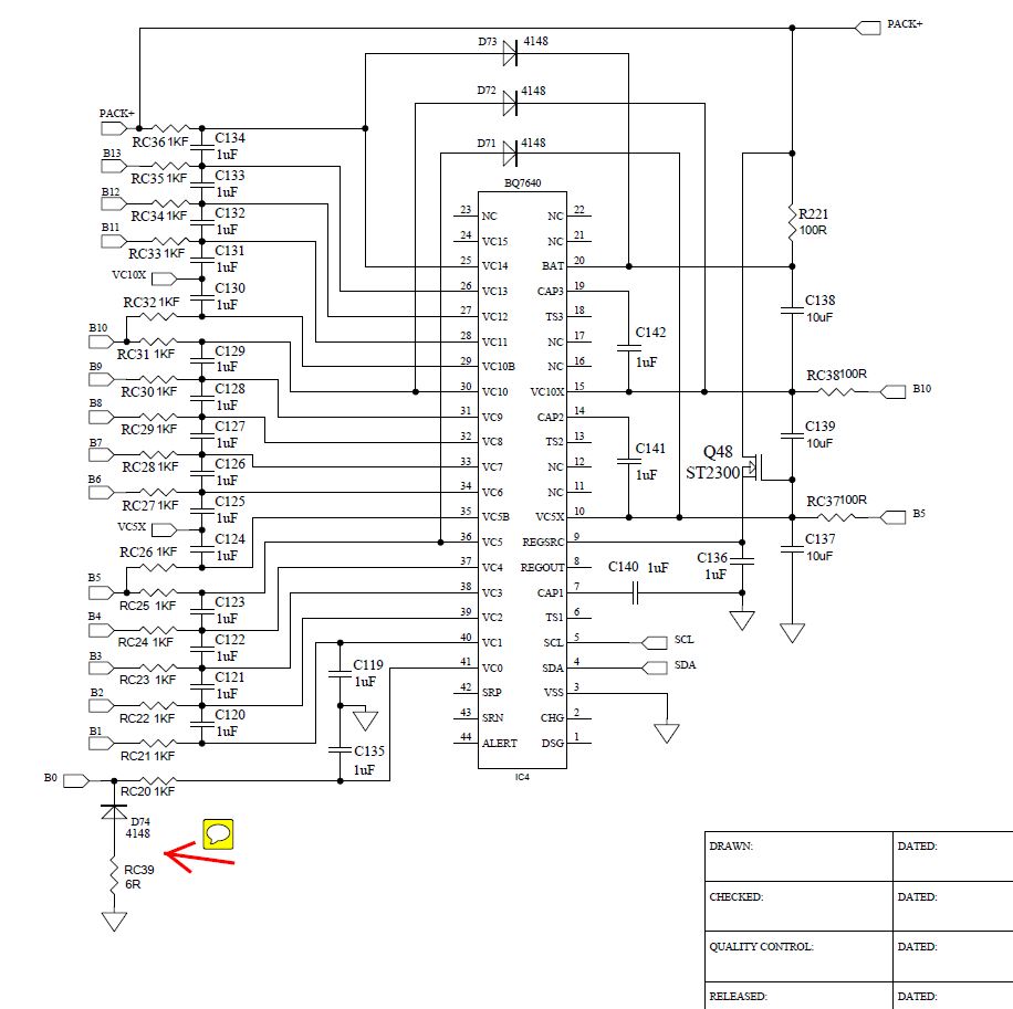
We would like to develop a high power charging system for a 14-cells battery, we are interested to make use of BQ76940 to track the voltage of each cell. Since we are implementing our proprietary charging algorithm in combination of special hardware architecture, therefore we are not using all features that are available from BQ76940. We simply use ADC features of BQ76940 to measure cell voltage and feedback the information to host system for further processing. Would you please help to review our design as outlined below and give us comments as necessary Thank you. Peter.


  • Hi,

    The schematic looks mostly correct, but there are some issues I will list below. I also recommend watching this video that covers how to connect each pin for the schematic: https://training.ti.com/how-create-schematic-bq76920-bq76930-and-bq76940

    • TS1 is the boot pin for the device. This pin needs a rising voltage in order to boot the device from SHIP mode. This app note discusses boot options in detail: http://www.ti.com/lit/an/slua769/slua769.pdf
    • If you are not using thermistors, you should connect the unused TS pins to a 10k pulldown resistor.
    • The ALERT pin should be connected to a 500k pulldown to VSS. You can also connect a 470pF cap across the resistor to filter noise. This pin alerts the MCU that a new measurement is available, but it also can be used as an input to indicate a fault, so you want to protect it from noise. You should connect it to the MCU to communicate measurements and faults.
    • Pins 11,12,16,17 all need to be connected (see the datasheet pin table or the video link). Pins 11,12 connect to CAP2. Pins 16,17 connect to CAP3.
    • If current sense is not used, SRP and SRN should be connected to VSS.
    • VC15 should not be left open. See Table 26 in the datasheet for how to connect the cells for reduced cell count. Since you are connecting 13 cells, this reference design for a 13 cell system might be helpful: http://www.ti.com/tool/TIDA-010030 
    • REGOUT needs a capacitor as defined by the datasheet

    Best regards,

    Matt