This thread has been locked.

If you have a related question, please click the "Ask a related question" button in the top right corner. The newly created question will be automatically linked to this question.

LM5118: LM5118MH/NOPB line regulation issue; I/P: 9V-36V , O/P: 28V Current: 1A

Part Number: LM5118

Hello,

We have used the LM5118 IC to derive 28V output from 9-36V i/p voltage. This circuit is followed by a schottky diode and a parallel combination of holdup capacitors (1300uF x 3). The holdup is later followed by load. We are facing an issue of instability in the buck boost output when an under voltage transient test(LDC 302 as per MIL-STD-704D) is executed. The detailed scenario is explained below.

When a under voltage transients are given at the input of buck-boost IC, The output is cutoff when the input transient of 7V is induced on the converter which is later taken care by holdup capacitors.

During this under voltage transient test, We are observing the drop in buck boost output to 22V and is sometimes further decreasing to 8-10V. This is causing our holdup to discharge quickly and our further circuits are getting turned off. One more thing is that the buck boost output is not recovering back to 28V after the input is recovered back to nominal voltage. We are not expecting this scenario to occur as per our design.

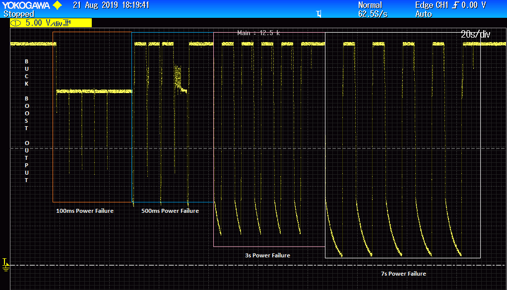
There is one more test (LDC 601 power failure test as per MIL-STD-704D) where a power failure of 100ms, 500ms, 3s and 7s are simulated. After a power failure of 500ms is executed, It is observed that our buck boost output is dropping to 22V. It is recovering back again after a power failure of 3s is executed. During this condition, It is also observed that our holdup capacitors are not completely discharged when a power failure of 500ms is provided though holdup capacitors are designed to withstand only 50ms failure.

This is primarily suspected as an issue with line regulation. Could anybody please suggest a few things that could solve the above problems.

Thank you.

  • Hi Pruthvik,

    Thank you for using the LM5118.  When you say "One more thing is that the buck boost output is not recovering back to 28V after the input is recovered back to nominal voltage", do you mean the output is never recovered or it just takes long time to recover? There are one factor that can keep the output under the regulation level: the circuit hits the current limit.  Since your circuit is turned off, each time it restarts it needs to go through the softstart, which can delay your output voltage recovery. Could you reduce the UVLO setting to below 7V, so the circuit can stay alive during line voltage transient?

    Anyway, we would like to review your schematic, and if you can show some key waveforms, they would help us in debugging.  

    Thanks,

    Youhao Xi,  Applications Engineering

  • Hello Youhao,

    Thank you for the reply. I tried implementing your idea of reducing the UVLO to below 7V. This solution worked fine and our buck boost output maintained a desired value of 28V DC even during Undervoltage transient condition. But we also have another issue as mentioned earlier. It is the drop of buck boost output to 22V when a power failure of (100ms & 500ms) is injected on to the input of buck boost.

    The oscilloscope traces captured are attached for your reference. I have also attached the schematics of buck boost section. There is a small change that is we are using the MOSFETS with part number STD70N10F4 instead of earlier NTD5865NLT4G MOSFET. This change was made to mitigate the radiated emission from the buck boost IC.

    Kindly let us know any possible solution for the same.

  • Hi Pruthvik,

    Sorry I do not fully understand the power failure issue.  When you lose input source, the LM5118 cannot supply any more current to the output, then the output will naturally fall.  So what is exact the problem that you want to solve?

    Thanks,

    Youhao

  • Hello Youhao,

    You are right. During Power failure of whatever the duration it is, the buck boost output falls; but it has to regain back to its nominal 28V when the supply is returned to normal condition which isn't happening in our case. The buck boost  output is dropped to 22V which is leading to further undesired issue with our unit.

    Please let me know if you need further more clarification.

    Thanks,

    Pruthvik 

  • Thank you.  I understand now. it seems the duty cycle is limited. 

    Can you try to increase R13 from 12.1k to 18.2k or even 28.7k, and let me know your test results?

    Thanks,

    Youhao

  • Before implementing the solution suggested by you, I tried removing the resistor R12 and ran the LDC302 test and LDC 201 power interrupt test. Though there was a drop of buck boost output to 22V when 29V transient was given, the output recovered back to 28V during the 22V input transient.

    Could you please let us know how could the removal of R12 resistor(connected between RAMP & VCC pins) allow the buck boost output to recover to 28V during power transient.

    Thanks & Regards,

    Pruthvik

  • Hi Pruthvik,

    R12 is only recommended for high Vin to to make sure the slope comp is adequate.  During startup, this may make the slope comp appear to be excessive. Note that the PWM comparator actually compares COMP and CS+SlopeComp.  So not much duty cycle is produced. 

    Instead of removing R12, can you test with a diode connecting VCC and VIN, with the Cathode on VIN and Anode on VCC?  This may help reset VCC during power cycling. 

    Thanks,

    Youhao

  • Hi Pruthvik,

    Can I assume the issue is resolved?  Let me close it here but you can re-open it by adding a new post.  If you have any updates, please let us known.

    Thanks,

    Youhao