This thread has been locked.

If you have a related question, please click the "Ask a related question" button in the top right corner. The newly created question will be automatically linked to this question.

LM25141-Q1: IC wont start up after running at high current limit

Part Number: LM25141-Q1
Other Parts Discussed in Thread: LM25141

Hello,

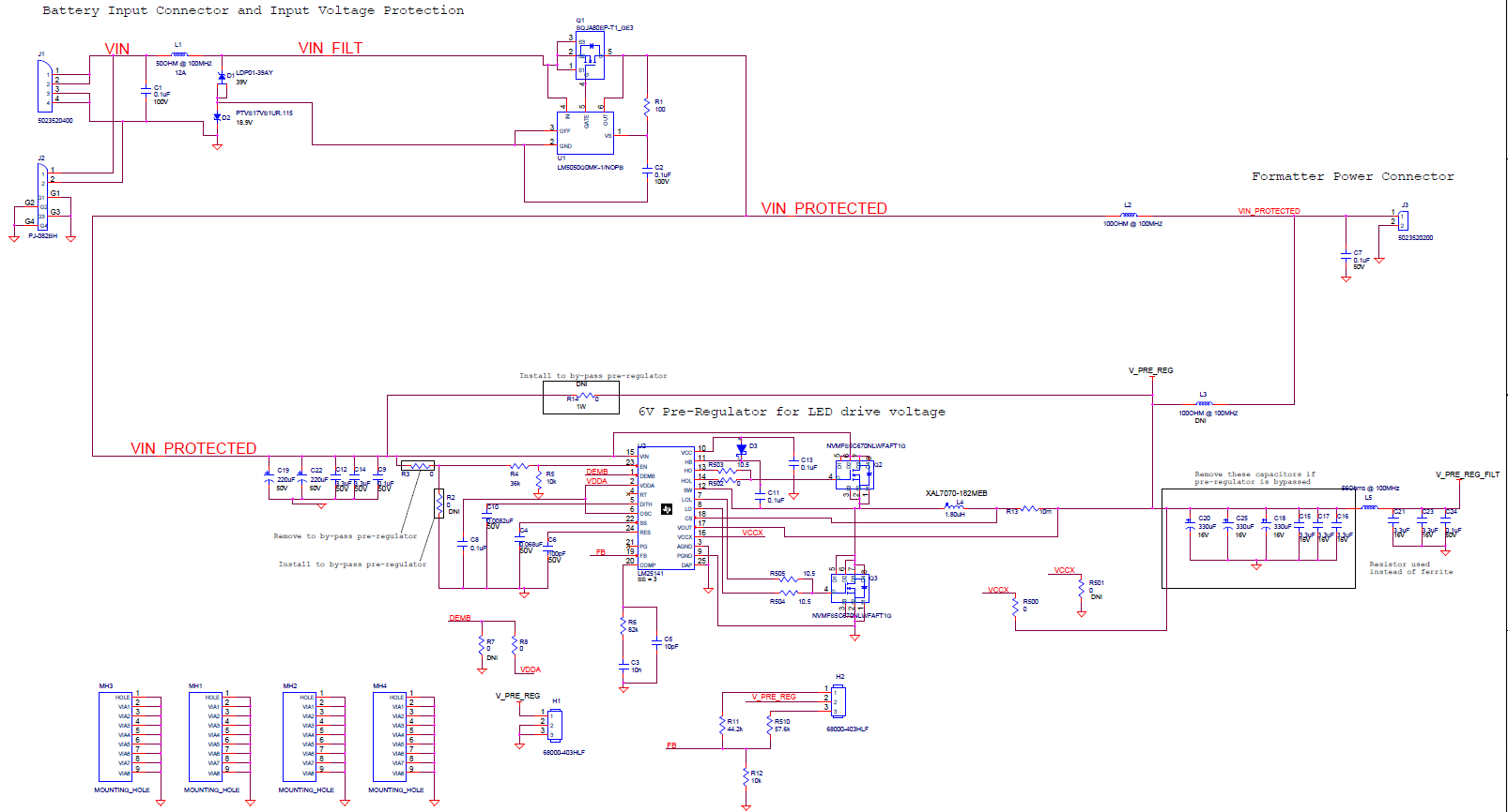
I am using this buck controller to pre-regulate an LED drive voltage.  Input is nominal 12V (8-18V) and output is 6.5V or 8V.  When running in 8V mode (for higher power LEDs) I was reaching the current limit of the LM25141 with a 10mOhm Rs (7.5A limit).  I was monitoring the temperature of the board and nothing was going above 50C, so I increased the current limit to 15A (there is a secondary current limit on the LED drive control).  The output current should really never reach 15A DC, only 6A DC.

After running for a few minutes, the temperature was still stable, but at some point the voltage cut out and the board shut off.  Now on startup the IC draws no current and I see no activity on PG, SW, or other output pins except VCC, which switches up to 5V.

Do you have any suggestions for where to check for the problem or what might have caused this? I have tried to test all the caps, inductors, diodes, resistors, and FETs on the board but they all seem to operate properly.

Thanks for the help,

Jackson

  • Hi Jackson, is the schematic available?

    Regards,

    Tim

  • Hi Tim,

    I have included an image of the circuitry around this regulator.

  • Hi Jackson,

    Here are the notes on the schematic:

    1. Vout of 6V should not be tied to VCCX - voltage is too high.
    2. VCC cap of 0.1uF is too low -- use 2.2uF.
    3. The inductor value looks high, leading to a very flat current signal. Usethe  value recommended by the quickstart calculator for the chosen shunt resistance.
    4. I wasn't able to find the MOSFET datasheet to verify that the gate voltage Miller plateau is in the 2-3V range.
    5. I recommend setting the low-side gate resistors to 0 Ohms to avoid possibility of cross-conduction.
    6. RES cap should be much larger than 100pF (e.g. 220nF) to set an effective hiccup delay during OCP.
    7. DEMB pin should be tied high or low for FPWM or diode emulation mode, respectively

    Please send a completed quickstart file for this design so we can review compensation. It's available by download from the product folder under "Design and Development".

    Regards,

    Tim