This thread has been locked.

If you have a related question, please click the "Ask a related question" button in the top right corner. The newly created question will be automatically linked to this question.

BQ76930: Separate path for charging and discharging

Part Number: BQ76930
Other Parts Discussed in Thread: BQ76940, BQ78350, BQ78350-R1

Hi All,

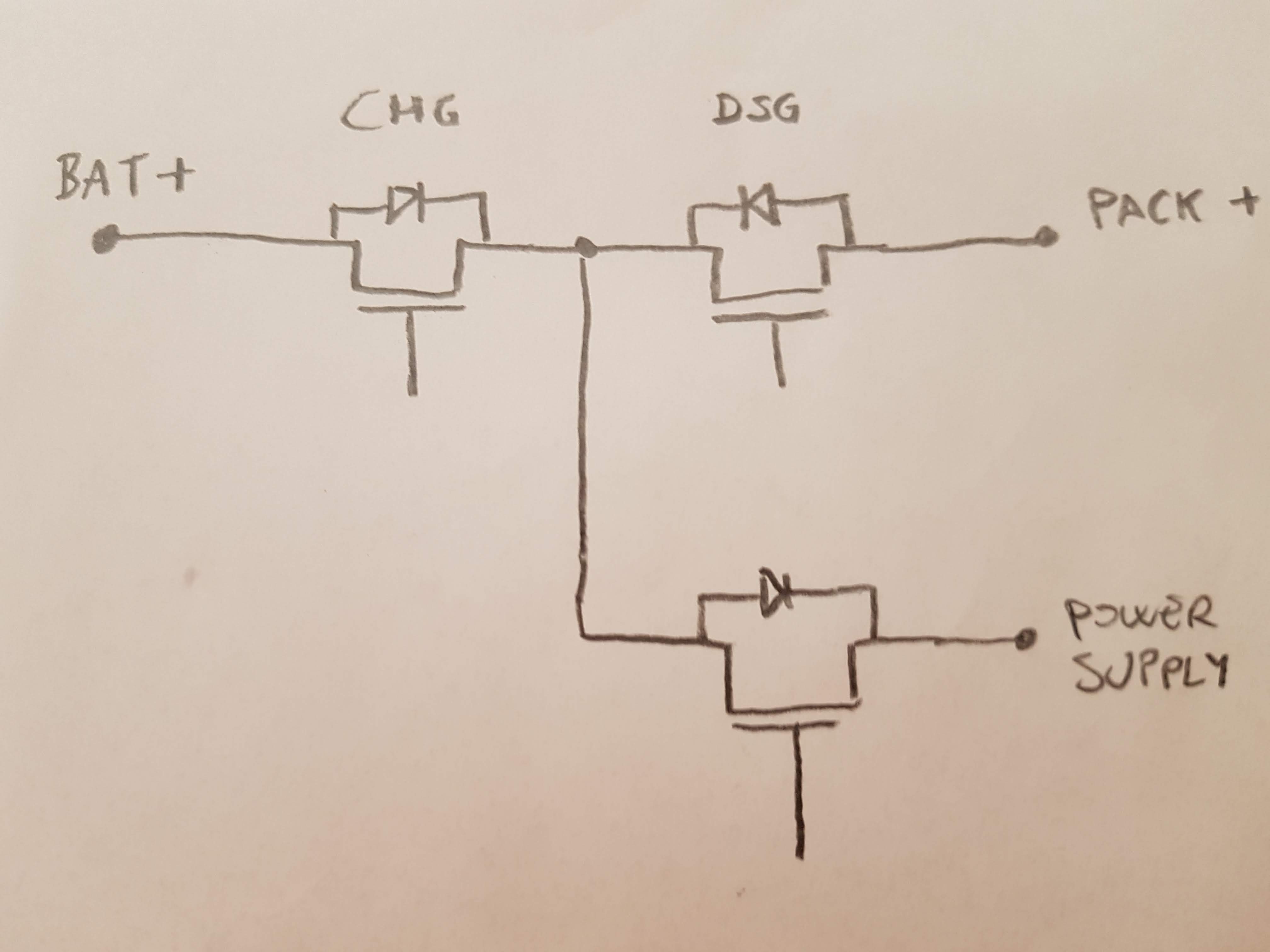
I am developing a BMS with BQ76940 and BQ78350. If I have separate connection for the load and the charger how can I design the circuit? I mean that I have one connection versus the load, in which the current flow is always outgoing and can be identified with the PACK+ and PACK- terminal of the evaluation board of 76940, and I have a deifferent connection for the input of the charger. Can be used the BQ78350 in this configuration?

Thank you,

Stefano

  • Hi Stefano,

    This configuration is very difficult with the BQ78350. It is intended for a series FET configuration. The main issue is the body diode protection feature which cannot be disabled. It is described in the BQ78350-R1 TRM in Chapter 3:

    If the CHG FET is off and the gauge detects discharge current ≥ Dsg Current Threshold, then the CHG
    FET is turned on to protect CHG FET body diode. The CHG FET is turned back off once discharge current
    is removed. If the DSG FET is off and the gauge detects charge current ≥ Chg Current Threshold, then
    the DSG FET is turned on to protect the DSG FET body diode. The DSG FET is turned back off once
    charge current is removed. Body diode protection is always active.

    The BQ76940 can be used in a parallel FET configuration, but it might be better to use an MCU to control the FETs in this case. This app note may be helpful since it has multiple different examples with parallel FETs: http://www.ti.com/lit/pdf/slva729 

    Best regards,

    Matt

  • Hi Matt, thank you for the reply. 
    Since I already have a microcontroller on the board for wireless communication, what do you think about the possibility to turn a mosfet placed from the power adapter positive terminal and the central connection of the CHG and DSG fet when the power suplly is connected? This should cause the BQ78350 to turn on the DSG fet too, but I don't think this can cause problems.

    The circuit should be like this:

    Stefano

  • Hi Stefano,

    I think this could work. However, it really depends on how your system operates. 

    During discharge, the body diode protection will sometimes turn on the CHG FET. In some applications this could be an issue because the charger contacts are exposed and could cause a safety issue. I think your proposed circuit solves this issue.

    During charge, the body diode protection will sometimes turn on the DSG FET. In some applications, the load is never fully off and this might be an undesired behavior while charging. Hopefully this is not an issue for your system.

    Regards,

    Matt