This thread has been locked.

If you have a related question, please click the "Ask a related question" button in the top right corner. The newly created question will be automatically linked to this question.

UCC28740: Output Loading transient issue

Part Number: UCC28740

Hi Team:

There are some questions that feedback from customer as below , please help to comment , thanks a lot.

condition:

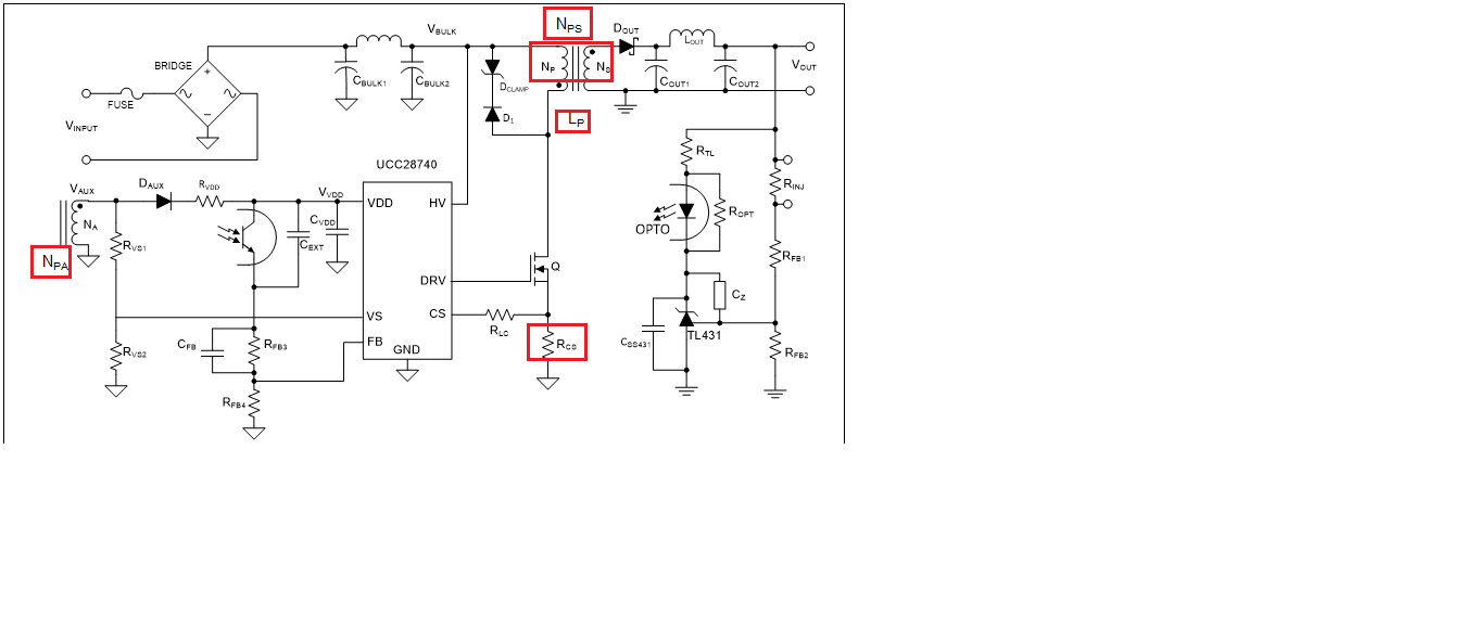
Vdc_in=120V~600V , Vout_1=15V/1.5A , Vout_2= -15V/0.2A  , schematic as attached.

DD-multi dc-190821.pdf 

1. RD use WEBENCH and Design Calculator for simulation, but result are different , Design Calculator  excel tool setup from RD as attached , please help to confirm.

sluc487b (crack)-15V-3.5A-190820.xlsx

2.VDD voltage follow load transient rise but not yet setup max load 1.5A , Vdd voltage already on maximum ratings , how could we improve it ? 

3.PCB layout as attached , please help to review it , if any cause operation issue , please help list and let us modify to improve it. 

H7600_MB_A-Red.pcb

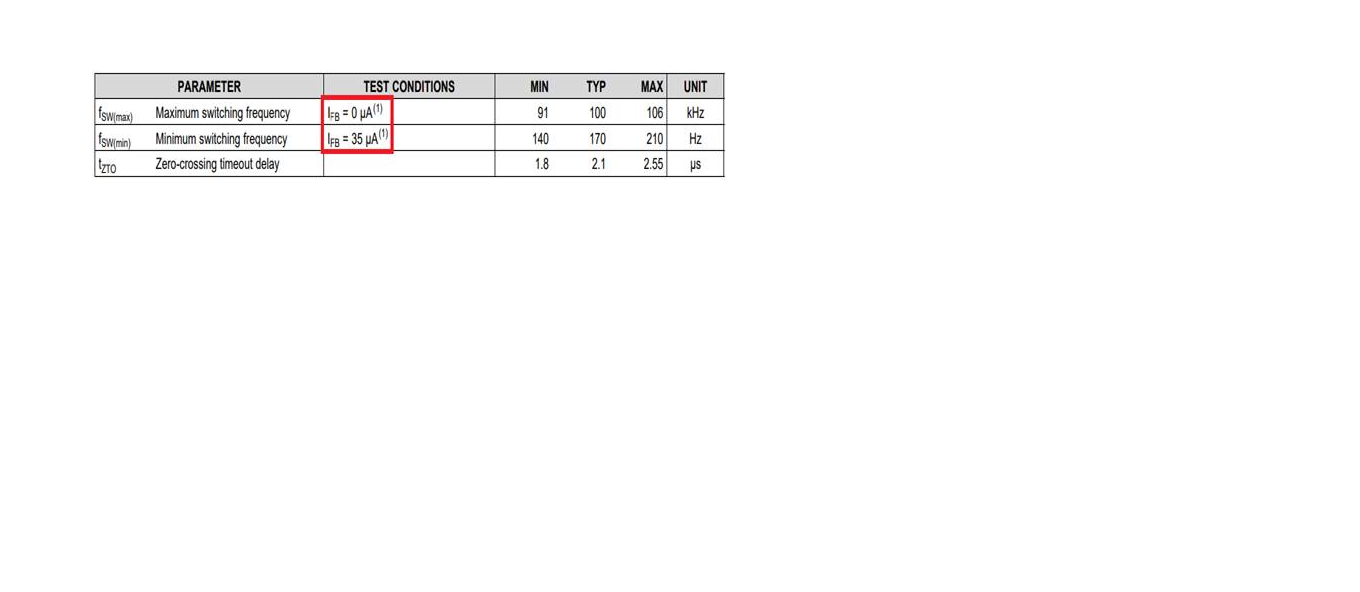
4.How could we setup frequency run up to 60~65K Hz ? transformer Lm setup , RD was not follow WEBENCH and  Design Calculator tool because of  core size issue 

5. How could we check CS pin waveform ? when probe connect to CS pin with noise and cause shutdown even use demo board to connect CS pin the same with  noise and shutdown as RD feedback. Is it very sensitive ?

Regards / Mark

  • You need check your schematics on a15 and a16 to see if their polarities labeled correctly.

    1. Where did you get the design calculator and its password? Your attached calculator is modified from its original after cracking on the sheet of (Calculation). But your modification is not complete as there are calculations from "START Here" page. I suggest you re-download the calculator from ti.com and do not crack it first and only use "Start Here" to input your specs, instead of cracking the sheet and doing incomplete modification. If you need something special which require to modify the formulas please contact us to move on, or it is difficult to find where you made wrong.

    2. please fix above "1" to see if this can be resolved.

    3. we will see your fix on "1" and "2" before doing this.

    4. That is in "Start Here" sheet.

    5. It sounds like your oscilloscope needs isolation, and if not, utility GND difference can cause the issue you have.

  • Hi Hong:

     I re-download the calculator from ti.com and sent to RD input their SPEC and RD feedback as attached , please help question as below , thanks a lot.

    sluc487b-pai190823.xlsx

    1.Primary and secondary turn ratio is lower than recommended Nps and remark on red word is "Using a lower Nps than ideal may result in deeper DCM operation at max load and may result in lower efficiency" -->it;s means only cause efficiency because of when max load may operate on DCM not CCM mode cause efficiency not good , Am I right?

    2.If current sense resistor select to high , it maybe cause OPP operation , Am I right ?

    3.If Lp lower than recommended , only OVP fault at high input voltage may result ?  have any other fault on Lp not enough ?

    4. Base on RD input SPEC and notice red word , as below picture , please help to analysis which cause VDD voltage follow load transient rise but not yet

    setup max load 1.5A , Vdd voltage already on maximum ratings ?

    5.How could we setup frequency run up to 60~65K Hz ? setup form Cfb ? 

    Regards / Mark

  • 1. If you pick up a turn ratio Nps lower, you will see several influences on the design parameters. Deep DCM is the most critical one to mention. If you fill in an arbitrary turn ratio you need to see what changes in the calculator to see if these changes are ok for you before move to the next fill in.

    2. Yes, it will get Iocc smaller.

    3. If Lp is smaller than recommended, the peak current may become always greater than needed during leading edge blanking, which will result in output over voltage protection.

    4.VDD voltage should be regulated by output voltage by turn ratio Nas of aux to secondary. Please make sure the turns ratio correct. You may use an oscilloscope to monitor aux winding output to check the turns ratio Nas correct or not. One possibility is your aux winding has too much leakage. In this case, you need to reduce leakage. Other less effective fix is to increase Rvdd. Or if you want to you can add a Zener clamp. One more thing is to check if you transformer polarity connected as assumed.

    5. This is calculated in the calculator. If you input your arbitrary values, the frequency will be resulted differently. In such cases. you need to first use default numbers and then use your arbitrary while monitoring the results. As this is DCM flyback, the switching frequency follows the simple equation Pin = 0.5 x Lp x Ipk^2 x fsw. So the frequency is setup by Lp and Ipk not by the IC but the frequency setup has to be in the IC specs.