This thread has been locked.

If you have a related question, please click the "Ask a related question" button in the top right corner. The newly created question will be automatically linked to this question.

UCC28064A: Load transient

Part Number: UCC28064A
Other Parts Discussed in Thread: UCC28064,

Hi TI,

I have load transient issue with UCC28064 at 264Vac.

Switching operation is abnormal. when increase load current dramatically. (100W-->700W or 0W-->200W)

This is not a problem when the input voltage is 90V.

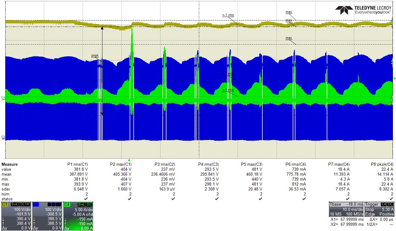
Yellow: PFC out, Blue: Vds_A, Green: Id_A

Could you give me some advice on the solution?


  • Hello Mason,


    Thank you for your interest in the UCC28064A PFC controller.


    When your system is operating at 264Vac input, the average output voltage is close to the peak of the line voltage (which is ~373Vpk).  The screen-shot data shows that the rms value of CH1 is about 382V.

    Since this is a dc level with some ripple on it, it also indicates that the average level of Vout is about 382V.  However, during a high load step Vout can sag very close or even below the peak of the line.  


    The high peak currents may be due to CCM operation (or direct line-to-output current if Vout falls below Vin_pk).  I think these high peaks are due to CCM.  And I think the CCM is due to loss of ZCD signal strength.  


    In the last low current half-cycle before the huge current peak, you can see several white gaps in the blue Vds_A switching waveform. This is due to loss of ZCDA signal to trigger a new switching cycle.  During inductor demagnetization, the ZCDx winding voltage must increase above 1.7V to arm the next cycle and when demag completes, it must fall below 1.0V to trigger the turn-on of the next cycle. The voltage of the ZCDx winding depends on the voltage across the boost winding.  When Vout is very close to Vin_pk, the ZCD signal may not be high enough to meet the trigger conditions for the next turn-on and switching stops.  If it stops, an internal restart pulse every 210us will try to restart switching.  So you see a series of white gaps about 210us wide, but in this half-cycle, switching could not be restarted until the input voltage dropped far enough below Vout.


    In the next half-cycle with the huge current peak, switching does restart and current builds up too high.

    I think this is CCM because the ZCDA signal is weak and allows the next switching cycle to start before the boost inductor current has fallen to zero. As Vout falls, the error amplifier drives COMP high and demands a long on-time.  The long-on time at high input voltage allows a high peak Id_A.  The low difference between Vout and Vin means that the peak current takes a long time to fall to zero.  The high peak current can pull down the Vin because of the input line-filter impedance and so there is enough voltage to get a ZCD signal, but it is not a clean signal and falls below 1V too soon.  This triggers a new cycle before the inductor current has dropped to zero, so CCM starts and builds up over several cycles.

    This cannot happen at low line.


    The peak current limit (at CS input) should prevent such excess Ipk, but I think it is not working because it probably has a too-large RC noise filter. The R value should not be greater than 100 ohm, the C-value should result in a time constant that is not too long.  Consider how much delta-Ipk you can get with maximum Vin_pk across the boost-L with an RC time-delay before sensing the Ipk level.


    I recommend that you expand the waveform to examine the switching cycles at the peak in greater detail, to verify CCM and look at the timing of the drain current with respect to the gate-drive signal.  Large super-junction MOSFETs also have a long turn-off delay due to Coss.  Also, examine the ZCDx waveforms to see if they are distorted.


    I suggest to increase the current sense resistor value a little to account for turn-off delay.

    I also suggest to decrease the RC time constant of the CS filter, and use 100ohm or less.

    I also suggest to raise the Vout regulation voltage by another ~5V to reduce the probability of Vout dipping too close the Vin_pk at 264Vac input.


    Regards,

    Ulrich