This thread has been locked.

If you have a related question, please click the "Ask a related question" button in the top right corner. The newly created question will be automatically linked to this question.

SM72295: SM-72295 NOT WORK

Part Number: SM72295
Other Parts Discussed in Thread: TIDA-00120, MSP430F5132

Dear sirs,

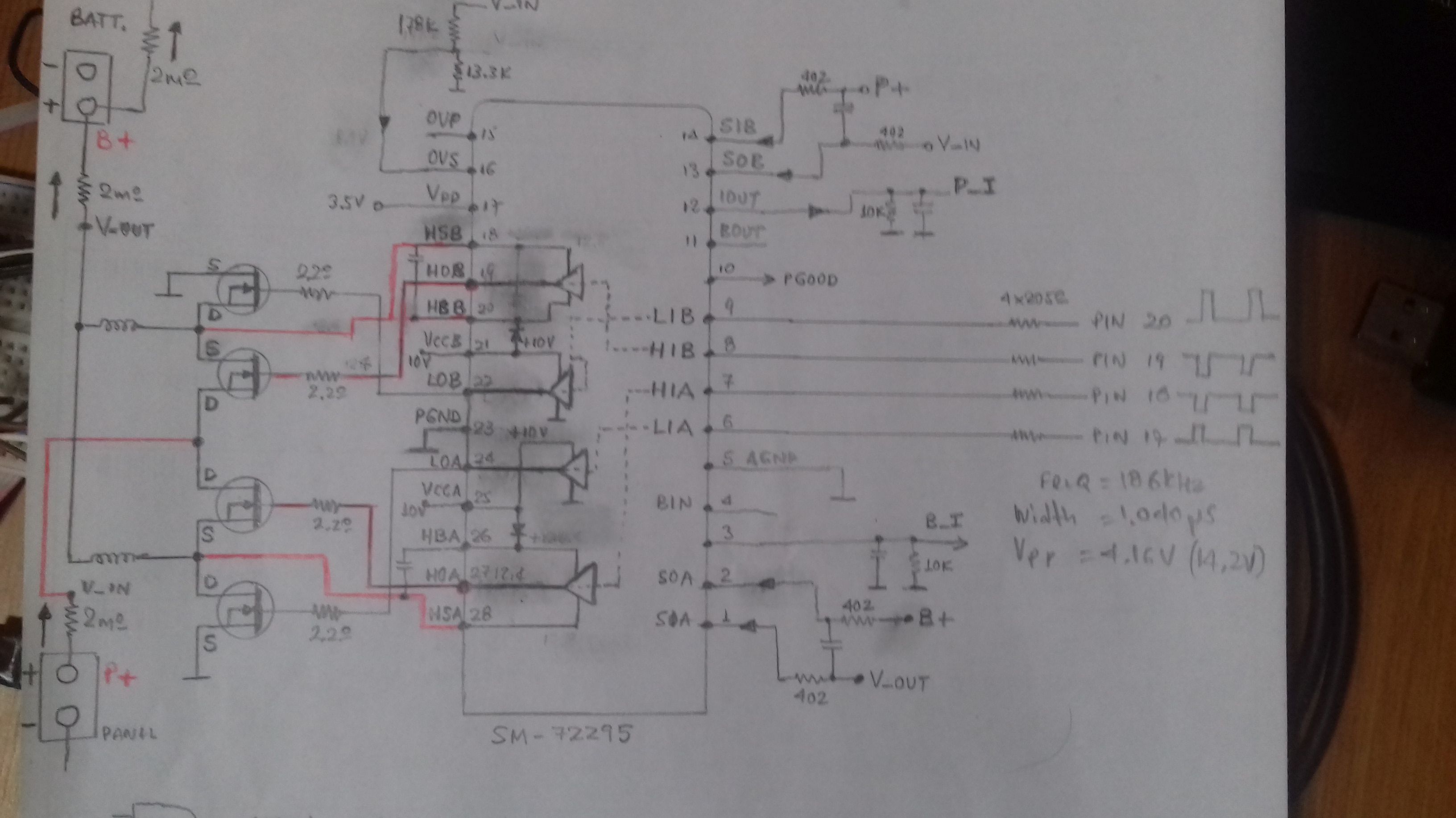
I  have a problem with SM-72295..The signals LIA,HIA,HIB,LIB at pins 6,7,8,9 is ok, but I have no output at HOA ,LOA,LOB,HOB, at pins 27,24,22,19...VDD=3.5V,  VCC=10.6V,  OVS=8.9V, PGOOD=3.5V...caps between HBA-HSA  and HBB-HSB are 0.47μF...the circuit is part of MPPT charge controller  PMP7605....in that test report, there is no the correct waveforms at LIA,HIA,HIB,LIB ..it will be very helpful ...instead of solar panel is a PSU at 14.0V.....battery 12V is connected for charging....can anyone explain me why SM72295 drivers not work ?

  • Hello Basil,

    Thank you for the interest in the SM72295. The VDD and VCC are within the recommended operating ranges. Confirm that the inputs are > than the maximum rising threshold of 2.3V. The OVS rising threshold is VDD +/-50mV, so if VDD is 3.5V the 8.9V you mention may result in an OV shutdown.

    Confirm if this addresses your question, or you can post additional questions on this thread.

    Regards,

  • Hello Richard,

    thanks for the answer..yes there was a mistake at divider before OVS pin . I was fixed that. now the drivers works, but I have abnormal mosfet operation when I connect the battery 12V...without battery connection the input waveforms amplified normal ..4.16V p-p input 14.2V p-p output ...freq.=168KHz, pulse width 1,04μS , ...no charge current ...the psu that I use instead of solar panel has interrupts even at 3A  current limit...psu at 14.0V.....the VCC at SM72295 (pins 21,25) is not stable ....I was checked the connections of 4 mosfet of buck converter...is according to schematic of Test report-PMP7605 RevA....mosfets ok..the first that I would like to know is the correct waveforms at inputs LIA,HIA,HIB,LIB....is there a design file or application note that has details of correct waveforms for inputs and output at that converter ? 

  • Hello Richard,

    In addition to my previous post, below is a sketch of the schematic to show the circuit around SM72295... Te mosfets are IPB034N06L3GATMA1, N-CH, 60V, 90A....The battery is 12V/10AH SLA.

  • Hello Basil,

    Thank you for the update, it is good to hear the OVS pin voltage allows the driver to operate. It is not clear why the VCC of the SM72295 is not stable, but it is possible this may result in operation problems.

    Can you try additional filter capacitance on the VCC to reduce the ripple, increase the voltage stability?

    There is a TIDA-00120 that references the PMP7605. I see this does show some waveforms. http://www.ti.com/tool/TIDA-00120

    I may need to refer you to an expert in these TI designs if this information does not help resolve the concerns.

    Regards,

  • Hello Richard,

    the waveforms at TIDA-00120 are for output stage....there is no info about input waveforms....because these waveforms are produced by the microcontroller MSP430F5132, I would like to know the correct waveforms at inputs LIA,HIA,HIB,LIB..., to find why the output stage with 4 mosfets works abnormal.... an opinion from TI designers of TIDA-00120 will be very helpful , or from anyone that have made tests with an evaluation board ( TI don't have for sale that board, and is not easy to copy that board)..

  • Hi Basil,

    Thanks for reaching out on e2e, I work with Richard.

    Check out the e2e thread below which goes over how the inputs on this TIDA work in more detail.

    Let me know if you have any other questions!

    Thanks,