This thread has been locked.
If you have a related question, please click the "Ask a related question" button in the top right corner. The newly created question will be automatically linked to this question.
Hi,
I'm designing a circuit using wireless charger BQ51003 and I would like to be sure that I designed it correctly. Here is the circuit:
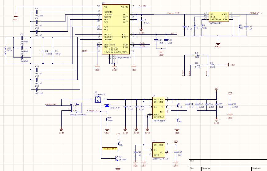
When battery is charging, microcontroller will sleep.
Do you recommend me to add something?
Thank you very much,
Jorge
Hi Jorge
See below check list for schematic review. TS_CNRL (F1) needs to be 10k resistor.
Also for layout use TIDA-00318 and TIDA-00669.
Things to check on your design:
Pin out of symbol, make sure it matches device
AD pin ground – if adapter option not used
COMM, BOOT, CLAMP and AC – Recommend reusing values from EVM / Application section
PGND connection -- verify good connection to ground
ILIM pin connection to ground thru FOD resistor -- verify current limit set point
FOD pin connection, 196 ohms good value to start, tune during fod cal
EN1 / EN2 Pin ground -- recommend adding 0 ohm to give you options
CHG pin LED, Open drain output
TS / CTRL Pin connect to gnd with 10k, safe condition good
RECT pin (AC1/AC2 full wave rectified signal), Cap bank to filter signal --- max voltage could be 15V to 20V. Note R20 value set during fod cal, 20k OK to start.
OUT pin needs 1uF (effective capacitance) near the pin. C7 - 2.2uF looks OK.