This thread has been locked.

If you have a related question, please click the "Ask a related question" button in the top right corner. The newly created question will be automatically linked to this question.

TPS2121EVM-023: Power interruption of TPS2121

Part Number: TPS2121EVM-023
Other Parts Discussed in Thread: TPS2121

Dear TI teams.

Would you like to give me advice about TPS2121.

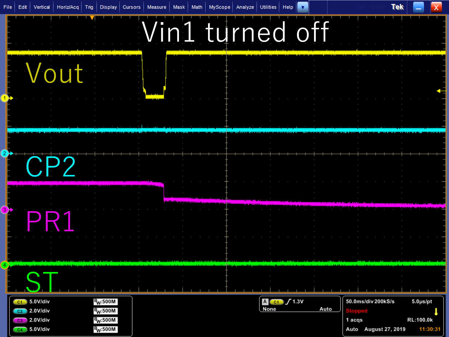
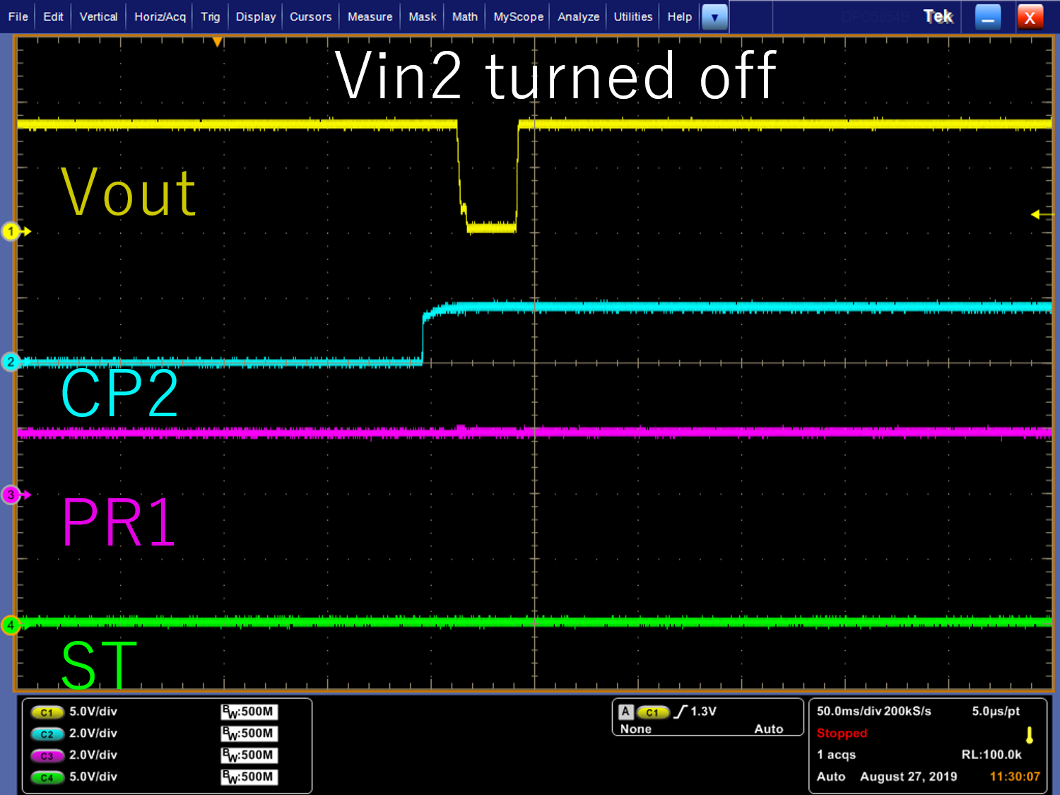
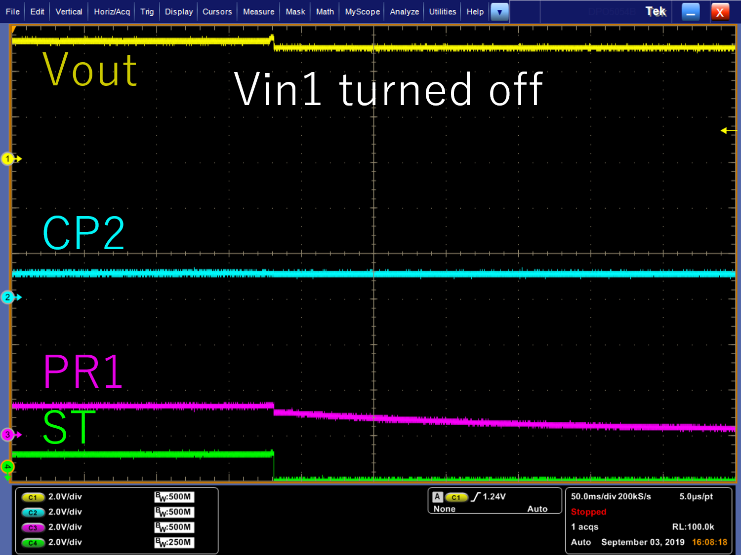
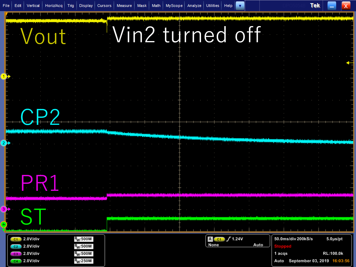
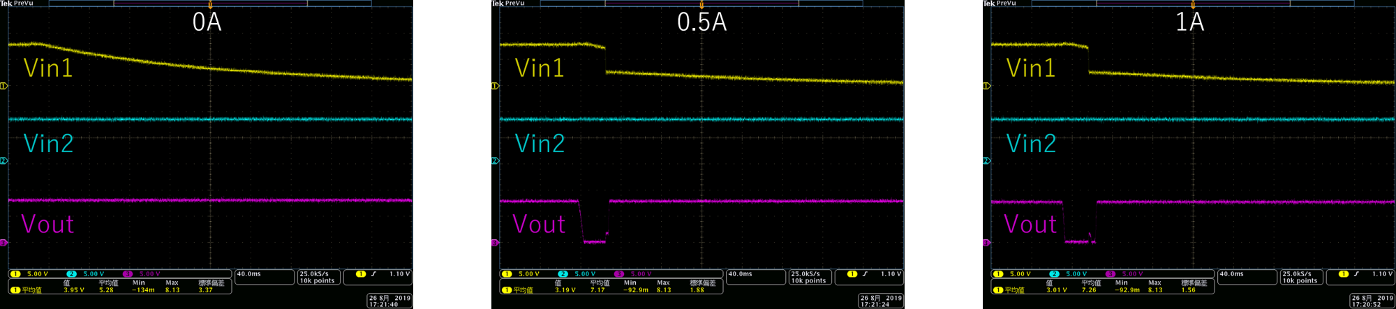
When switching voltage, It occurs voltage drop like a pictures.

Does not occur when there is no load

Vin1 and Vin2 are 8V.

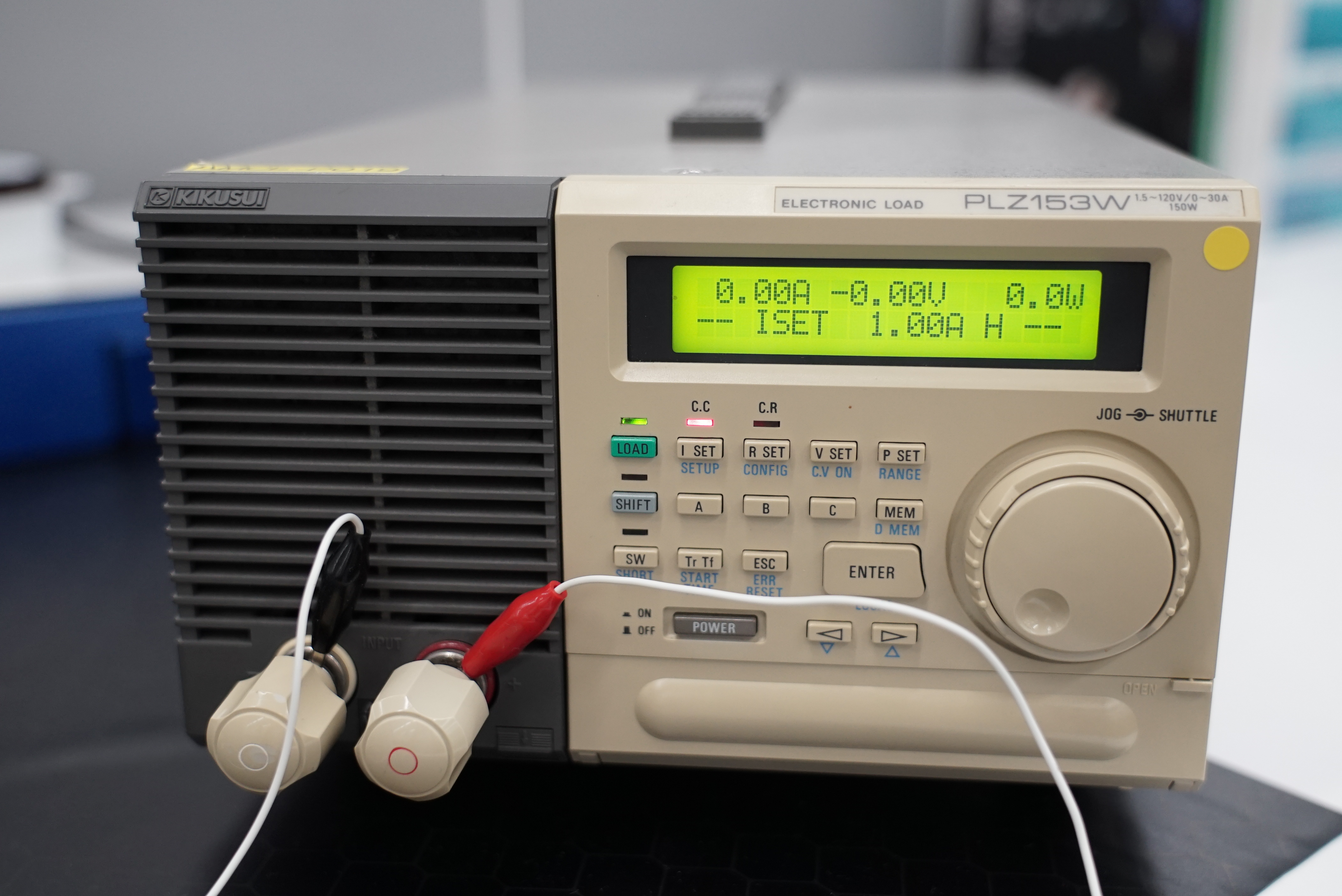
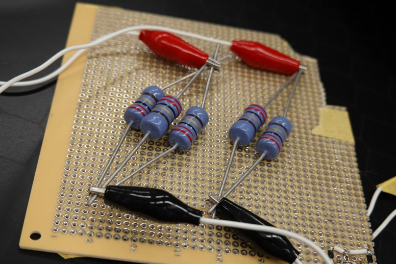
Pin arrangements is in a picture.

Hideyuki Tobata

  • Hi Hideyuki Tobata,

    By your testing methodology, I am assuming you are running this device in XREF mode. 

    I also see that your issue is exaggerated in the 1A case. I have a few questions about this.

    1. Can you please let me know what load your are powering?

    2. Using this same load condition can you probe PR1, CP2, VOUT and ST on one graph while making the switch?

  • Hi,Shreyas Dmello

    Thank you for replying.

    I want to ask your questions.

    1.I used electronic load like the picture.

    2.This is waveform 

    Vin1,Vin2 and Pin arrangement is same condition as last time.

    A load is 1A.

    Hideyuki Tobata

  • Hi Hideyuki Tobata,

    Unfortunately, it looks like you have left the ST pin grounded. Could you please move jumper JP2 to jump between pins 1 and 2? This will help us figure out when the channel switch occurs.

    Also we have noticed a lot of transient issues with electronic loads and how they respond in a constant current mode. Is it possible for you to use an equivalent resistance?

    To further eliminate variables, can you please run IN1 and IN2 at 5V as well? This will make sure that the resistor divider network you are using is correctly configured for the supply voltages?

    Finally, in your second scope shot you state that VIN2 is turned off but CP2 rises to a high voltage at this time. I am not seeing how CP2 can rise from low to high voltage when IN2 is removed.

    Could you please rerun these tests with the changes and get back to us?

  • Dear Shreyas Dmello

    Thank you for your advice

    I'm sorry for the mistake about ST pin.

    I reran test board as your advice. Vin1 and Vin2 are 5V.

    I used equivalent resistances of 1A load as a picture.

    And I checked the waveform again with an oscilloscope.

    I think it is working

    Thank you for your help

    Hideyuki Tobata