This thread has been locked.

If you have a related question, please click the "Ask a related question" button in the top right corner. The newly created question will be automatically linked to this question.

LM74700-Q1: reverse polarity protection + load switch + bidirectional current

Part Number: LM74700-Q1
Other Parts Discussed in Thread: LM5060,

Hello support,

I am designing a power path for high current 20A~30A and wide input voltage 10v ~ 40v

The application requirements call for

1. Reverse polarity protection

2. Load switching

3. Inrush, OVP/UVLO and Transient protection

4. Bi-directional current control

There is a dual charging input with source selection and no current sharing ...

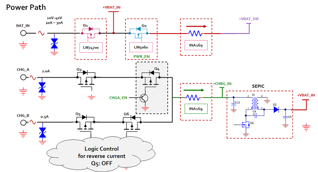
I could use either #LM74700 or #LM5050 I suppose to ORing the chargers. But I will need a back-to-back FETs for source selection.

Now, since the charge path has a relatively low current rating (2A max), I was planning to use PFET with some discrete transistor logic to allow charging / disable PFET for reverse current protection when two chargers are plugged in. The downside is adds design / debug complexity 

One possible scheme I am considering is depicted in the diagram below. However, according to the datasheet, the LM74700 also block reverse current so I am not 100% if this will work.

Alternatively, I could bypass #LM74700 and feed SPEIC output to BAT_IN (PWR_EN = LOW). In this case, Q4 (with some logic) acts as reverse polarity protection in the event the battery inputs are reversed. 

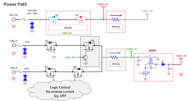
Another scheme is to use a single #LM5060 and drive the NFETs. However, it must be be enabled (PWR_EN = HI) to allow charging while the system is OFF,  however this means higher quiescent current and battery drainage....

Again, I could bypass #LM5060 and feed SPEIC output to BAT_IN (PWR_EN = LOW). In this case, Q4 (with some logic) acts as reverse polarity protection in the event the battery inputs are reversed. This looks like the most cost effective option but requires small signal diode Or NFET from LM5060 GND pin to GND. Do you see a problem with this approach?

Q1) Can you please confirm if the LM74700 can be used with bidirectional current applications?

Q2) The charger input are 12v~24v do you have a suitable solution that meet the above requirements?

thank you!

Alex.

  • Hi

    To allow LM74700-Q1 in bi-directional blocking application, we need to have additional circuitry to enable the reverse current when desired (during charging).

    Let me get back with the circuit proposal for this by end of the week.

    Regards,

    Kari.

  • Hello Alex,

    To use LM74700 in bidirectional application, it needs to allow reverse current when desired.

    To allow LM74700-Q1 to conduct reverse current, connect a 100 ohm resistor between cathode of IC and drain of the power MOSFET (Q1). 

    Next between cathode of IC and GND add a 1Kohm resistor and a signal MOSFET(Q2) to disconnect when reverse current blocking is required.

    When the MOSFET is turned ON, it should connect a 1kohm resistor from cathode pin to GND. This will draw current through 100ohm resistor and increase the reverse current threshold, thereby allowing reverse current to flow when the signal MOSFET(Q2) is ON. When Q2 is OFF, circuit functions normal and can block reverse current.

    Regarding the whole topology, I would provide detailed feedback by early next week.

    Regards,

    Kari.

  • Hi Kari,

    Thank you for getting back to us on this. It's much appreciated. 

    If I understand you correctly, the LM74700 and supporting circuitry are depicted as below.
    I believe the LM74700 must be enabled for this to work.


    Now, suppose the circuit works as expected, what is the set maximum reverse current possible with 100/1k ohms.

    Also, I have not simulated the circuit, but what happens when VBAT polarity is reversed while the system is OFF?
    If the diagram above is correct, the body diode of Q2 is forward biased and the reverse polarity protection would be compromised. 

    Can you please confirm?

  • Hi Kari,

    When can we expect an answer on this thread?

    1) What is the set maximum reverse current with 100/1k ohms ?

    2) can you please confirm the suggested reverse polarity mod would survive reverse polarity protection?

    3) For the charge path, the LM76202-Q1 seem like a good solution with added feature,  
    can you please confirm device availability ?

    Regards,

    Alex

  • Hello Kari,

    Any chance we get a response on this? I'd appreciate your feedback.

    Thanks...

  • Hello Alex,

    I am reviewing this design question and will get back in the next couple of hours.

    Regards,

    Kari.

  • Hello Alex,

    Answers to questions on reverse current / polarity.

    1) What is the set maximum reverse current with 100/1k ohms ?

    <Kari> With 100 ohms, cathode will be 1.2V below drain of MOSFET. Maximum allowed reverse current is -(1.2 + 0.011) / RdsON of MOSFET , here -11mV reverse trip voltage needs to be added. For a 5mohm MOSFET, reverse current allowed -1.211/0.005 = 242A. May be too high. you can change the resistor values as you need based on above calculation.

    2) can you please confirm the suggested reverse polarity mod would survive reverse polarity protection?

    <Kari> Adding a small signal diode rated to 40V in series to 1kohm would protect the circuit when system is off (to enable charging)

    3) For the charge path, the LM76202-Q1 seem like a good solution with added feature,  

    <Kari> Yes, LM76202 or Lm74202 would best fit for charging path to replace Q3+Q4 and Q5+Q6.

    Design with LM74700-Q1 (1st option) seems to be best fit.

    Regards,

    Kari

  • Hi Kari,

    Thank you for getting back to us on this. This answers my concerns. 

    The design now can be much simplified. 

    Best,
    Alex