


Hi,
I'm using the LM27762 to generate +3V and - 3V from 5V (USB generated). I have used as guidelines the schematic and layout provided in the LM27762 EVM user guide and modified the values of resistors and a couple of capacitors (find attached the pic of the schematic and layout)
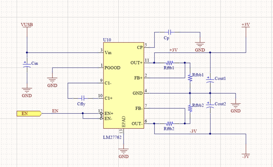
Schematic:
Components:

Top Layer - Signal:

Layer 2 - GND:

Layer 3 - PWR:

Bottom Layer - Signal:

PCB Picture:

I have also bought the EVM Module to compare the noise performances and also to understand better how the LM27762 works. However, on my PCB, the output voltages are not correct: I measure +2.8V and -2V instead of the +/-3V.
I measured with the scope the signals at Cp and at Cfly and at the outputs. There is definitely something wrong with the switching:
Cp (this signal only is AC coupled):

C1+:

C1-:

Vout+:

Do you know what's going on?
Thanks for the help


