This thread has been locked.

If you have a related question, please click the "Ask a related question" button in the top right corner. The newly created question will be automatically linked to this question.

UCC256302: UCC256302 FB PIN

Part Number: UCC256302

Hi Tiers:

I have some questons about the UCC256302 FB PIN, Can you help me understand them, thx

1,  can I add a resistor between Pin FB and GND to achieve constant power after overload?

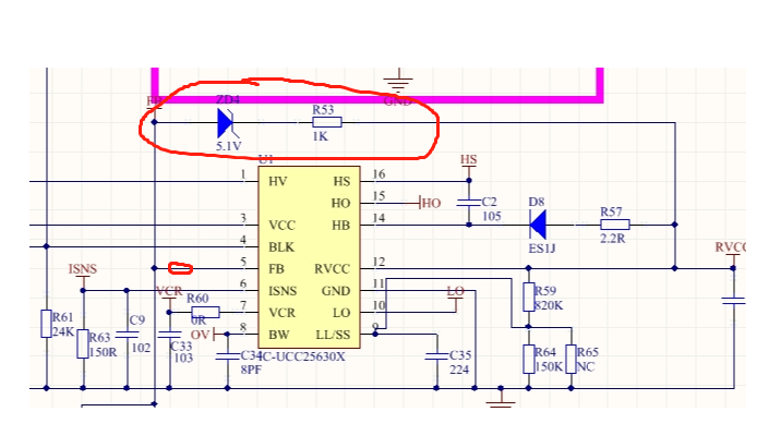
2, what are the ZD4 and R53 (see the SCH) effect, can I remove them?

  • Jack

    I assume you will still have the optocoupler collector connected to the FB pin as well as a resistor to GND. I'm not sure adding a resistor will do what you are hoping to.  The FB pin is designed to be connected directly to an optocoupler.  The way it works is that as the optocoupler changes the amount of current that it sinks from the FB pin, the amount of current from the internal current source at the pin that flows towards RFB changes.  This voltage is then used to adjust the operating point to vary the output voltage.  Adding a resistor will add a constant load on the FB pin, so the operating range of the feedback will be reduced and shifted.  It won't just add the clamp you are hoping for.

    ZD4 and R53 are used to prevent optocoupler from saturating by acting as a clamp.  Section 5.2 (page 8) of the following app note goes into detail about this http://www.ti.com/lit/an/slua836a/slua836a.pdf.  If your design does not have transient that is severe enough to cause the optocoupler to saturate you can eliminate it.  We have example reference designs like http://www.ti.com/tool/PMP21683

    Best Regards,

    Eric