Other Parts Discussed in Thread: UCC256302, UCC256303, , UCC256403
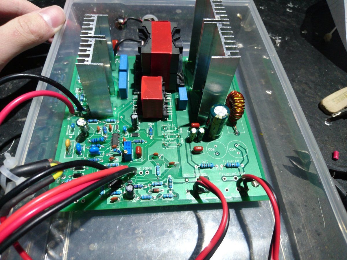
When input 230v AC and 390v DC input to the system it draws arround 13mA from the 390V.
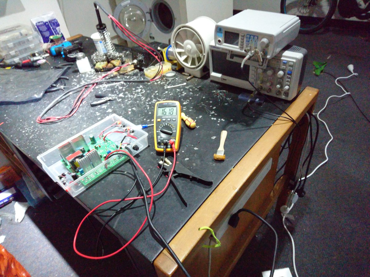
However no VCC voltage is genereated when AC is pluged in , the VCC voltage stays at less than 0.2V.
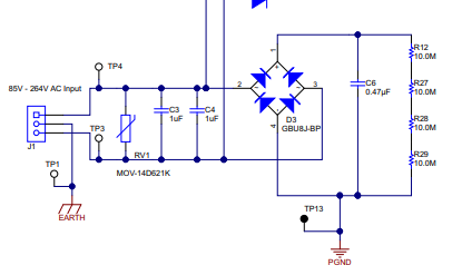
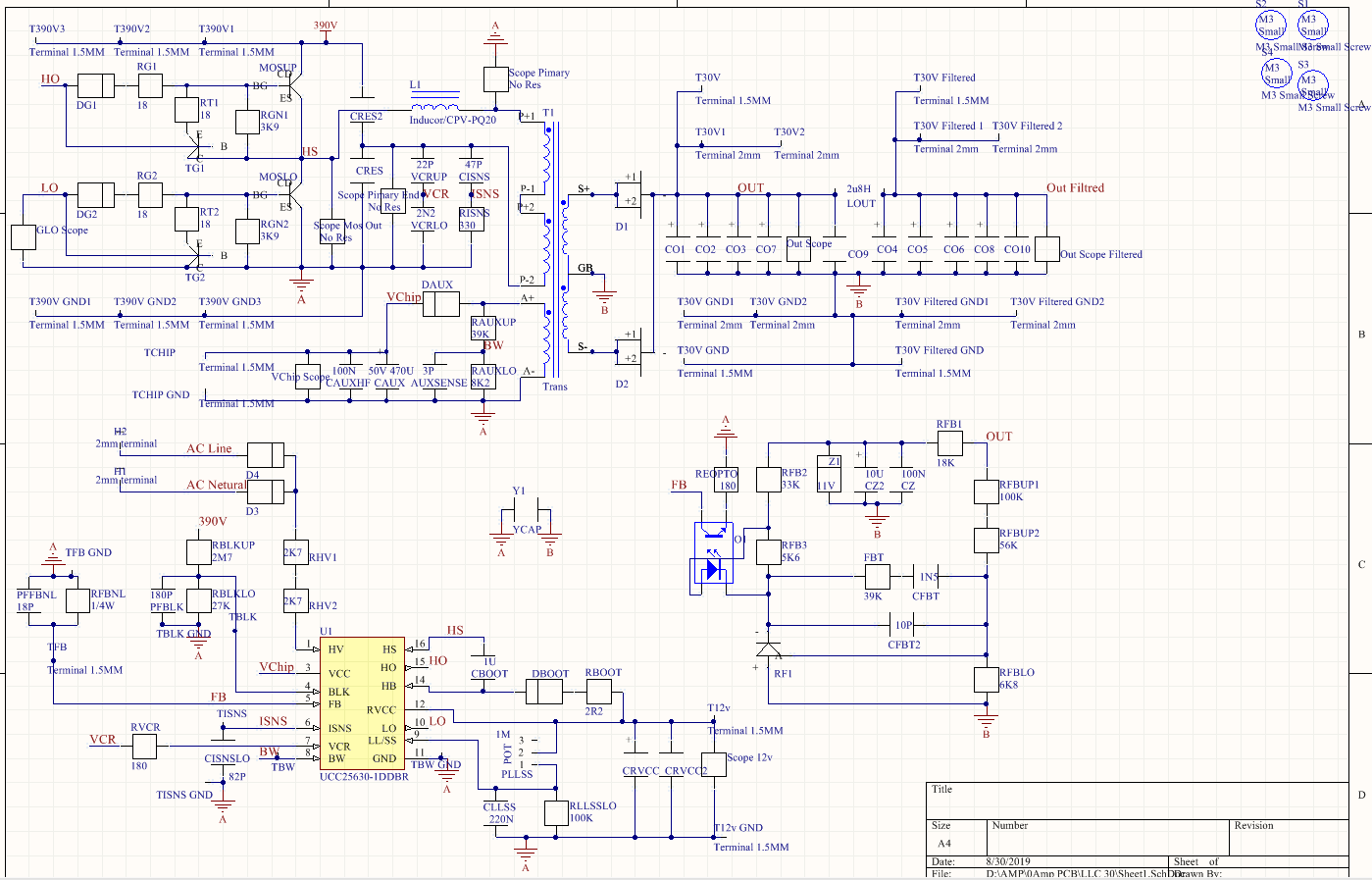
The BLK voltage is 1V with the 2M7 upper and 27k lower resitor divider, 390v input. With not working HV startip function
With the 1.2M and 56K lower resistor I got 2.8V BLK and 1.5V at the VCC pin, I'm guessing VCC is being charged by BLK pin.
Can someone please tell me the prolbem.
This is a final year project over 1 year time and is due eary October. Hopefully not fail becasuse with proper explanaition and work put in even not woking projects can get the pass grade.
I have allot of innovations in amplifier area and is bit shocking for me personally not being able to get the LLC going at all.
This design will be implemented in a audio amplifier low noise supply for a company, it will be selling within few years time and if I don't get this working I will chose diffrent toploligies to substtidue.
Is it because the PFC has to turn on before the LLC can start and I need to change to a UCC256302 chip. Which I think unlikley
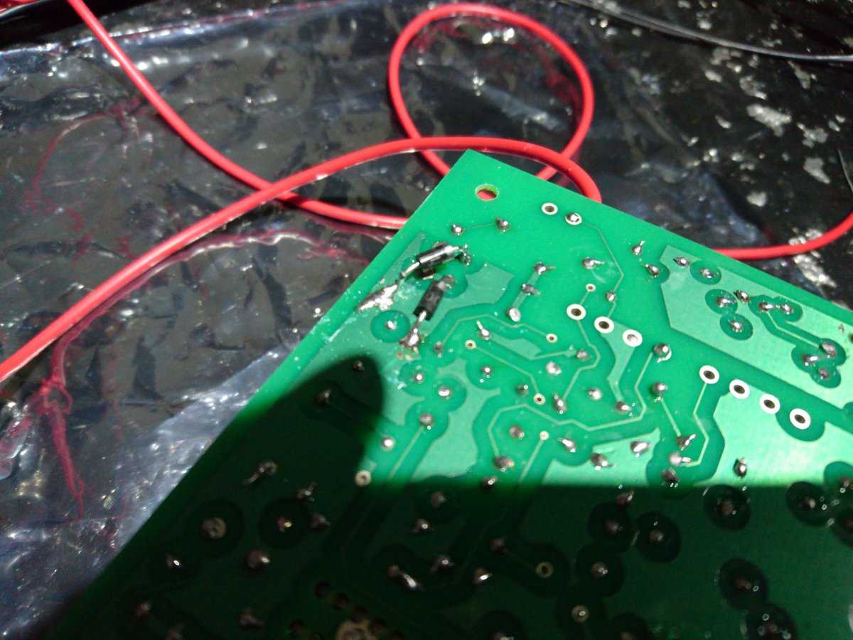
Or is it becasue the system requires the external circuitry on the 230V which I do not have, I only have two diodes and two 1/2W resistor feeding to HV pin from 230v AC.
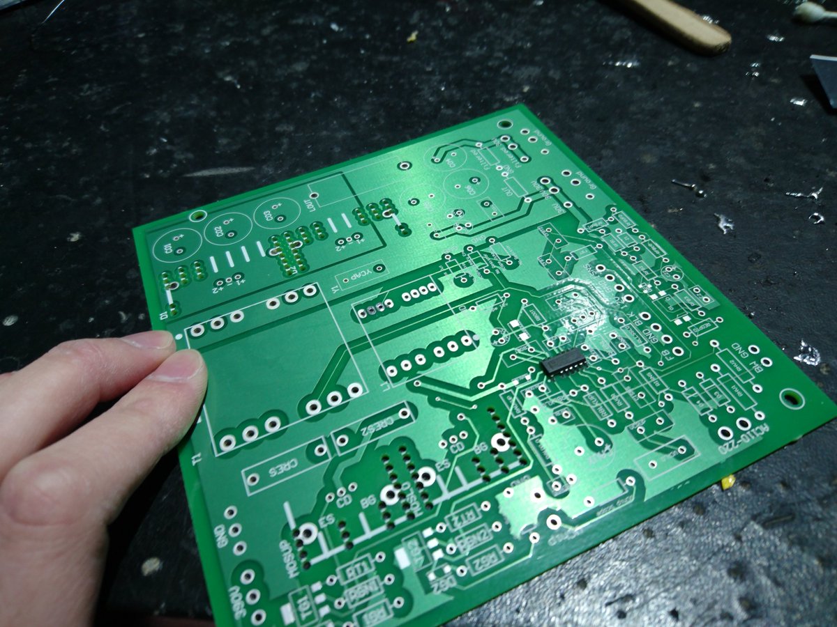
1st time I thoguht I damaged the device through ESD and soldering too hot manually.
Used a pick n place SMD machine and proper SMD oven to get the whole thing rebuilt
Also used moderate ammounts of ESD precautions with anitsatic wrist bands, mat and connecting GND of LLC to Mains via 1M when installing.
After rebuld still dosen't work.
Me and the PHD lecture has zero idea on the prolbem and how it can be solved......