This thread has been locked.

If you have a related question, please click the "Ask a related question" button in the top right corner. The newly created question will be automatically linked to this question.

BQ51050B: Wireless Charging Qi Receiver Coil orientation distance problem/s

Part Number: BQ51050B
Other Parts Discussed in Thread: BQ24040, BQ51221, BQ51021, BQ51020, BQ51013B, BQ51010B

Dear Support

I am working on a design that requires Qi & NFC

I have used BQ51050B IC to implement Qi Receiver circuit.

I have used the dual coil from Wurth:

https://katalog.we-online.com/pbs/datasheet/760308103307.pdf

One of this coils is used for Qi Rx

2nd Coil is used as NFC antenna

I measured the Ls & Ls' of coil and calculated the respective Capacitor values

So far,

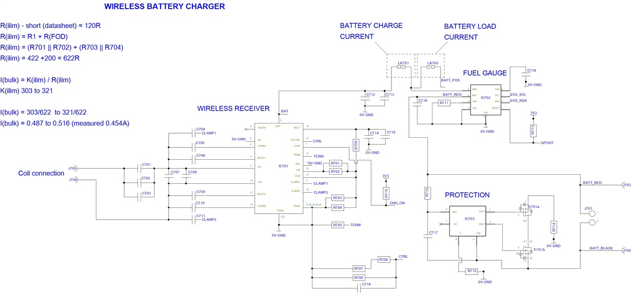
the Qi receiver side works "fine" as in the Battery (1200mAh) gets charged BUT as long as the the Coil sits flat and flush with the surface of Qi charger (Although the fast current measured (as measured by Fuel Gauge IC BQ27421 = 0.454A instead of expected 0.487A to 0.516A)

If I add a 2mm thick plastic (I used a sleeve from Mobile phone cover) in between the Charger surface & my Receiver coil then the Charging does not start. ( In actual application the circuitry would need sitting inside a mechanical enclosure but as it is 3D printed at the moment and I was not sure about the precise thickness of material so I used a plastic sleeve from Mobile phone protection cover) 

** Coil sits flat on the plastic sleeve as well (so it is not sitting at any inclined angle)

(I measured Ls' with that 2mm gap)

My 1st question:

How do I fix this distance problem as I was expecting Qi Rx to work even when coil is 2mm to 3mm away from the Charging Base surface?

So far, the whole design is based on theoretical calculations (formulae form datasheet) for the two Resonant caps values that I have fitted. I have not used any other calibration methods

I understand (from one of the videos on TI training section) that in order to work our Qi Rx with any Qi transmitter, it needs to be FOD calibrated. and the method involves purchasing 

AVID Technologies QI FOD transmitter & use it with FOD calibration tool from TI 

& searching it online it seems to be out of stock with lead-time of 8 months.

My 2nd Question:

Are there any other recommended cost effective methods available to perform the FOD calibration? As AVID module is on 8 months lead time. Do Qi Rx designers using TI's BQ51050B have any other option to do this calibration?

Now, regarding the Dual coil,

The NFC coil (metal) would always be exposed to Qi Transmitter (Charger). We would be using either NFC or Qi at a given time. But,

My 3rd question:

Could Qi Charger Transmission (energy) be picked by NFC coil & consequently could it damage the NFC related circuitry on my board?

I am happy to share the Full schematics & layout of the product and more details about the product if you could share the technical support team's email here.

Looking forward to hearing from you,

Kind Regards

NS

  • Also another question, 

    I was going through the comments in following post:

    https://e2e.ti.com/support/legacy_forums/wireless_power/f/693/p/596500/2219830#pi320995=1

    Hi Carlos
    Something is wrong with the set-up or data, as current is increased we should see the PPT and PPR both increase but they are flat from 100mA to 200mA. The problem may be the battery emulator. 
    Another battery emulator to look at is in the bq24040 User's Guide:
    www.ti.com/.../sluua77.pdf

    Current measurement should be all current out of the bq51050.

    Best Regards,

    Bill Johns,  Applications Engineer

    Texas Instruments Inc

    Dallas, Texas

    ***********************************

    In the above post, it is stated that:

    Current measurement should be all current out of the bq51050.

    If I were to use the battery emulator as suggested in 

    http://www.ti.com/lit/ug/sluua77/sluua77.pdf

    How would I vary the current (I_Load) from Min to Max for FOD calibration of my Rx circuitry?

    As the FOD calibration manual states to set R(ilim) to fixed values

    Set the ILIM to a high value to avoid current limiting during calibration (for example1.3A)


    • Start with setting RFOD to approximately the default (see EVM user guide for default values) with variable resistor (RFOD), and set Ros OPEN (ROS1 and ROS2). Here is a list of default RFOD values by device:
    o bq51221 RFOD default value is 480 Ω
    o bq51021 RFOD default value is 495 Ω
    o bq51020 RFOD default value is 495 Ω
    o bq51013B RFOD default value is 196 Ω
    o bq51003B RFOD default value is 196 Ω
    o bq51050/1B RFOD default value is 200 Ω
    o bq51010B RFOD default value is 200 Ω

    Would it need adding a Potentiometer for  my R(ilim)? i.e., R701 & 702 to be replaced by Potentiometer in above schematic? 

    And varying the POT to achieve different charge current values? OR is there another way of achieving it?

    Kind Regards

    NS

  • And another question:

    (hoping that someone from support team will answer this query)

    Could Qi sniffer (along with an off the shelf Qi charger) be used as an alternative to calibrate the receiver for the following two cases:

    1) To be able to use our product with any charger after that?

    2) To be able to use our product with that specific charger that we use during calibration (3rd party but we could use it as part of our package)?

  • Hello NS

    Alternative to Avid FOD TX -- This will depend on your application and plans for product.  If the RX will only be used with your TX and NO Qi certification is required then a customer calibration can be done. 

    The problem with an off the shelf TX used for calibration is the accuracy of transmitted power measurement (PPT), not good enough for Qi calibration.

    I would like to discuss this off line we have the option to discuss this off line, look for a message from me.

  • Hi N S

    Working with you off line on this question and will close this post for now, can reopen later if needed.