This thread has been locked.

If you have a related question, please click the "Ask a related question" button in the top right corner. The newly created question will be automatically linked to this question.

UCC2897A: UCC2897A power up failure (PVDD power not stable)

Part Number: UCC2897A

Dear Sir,

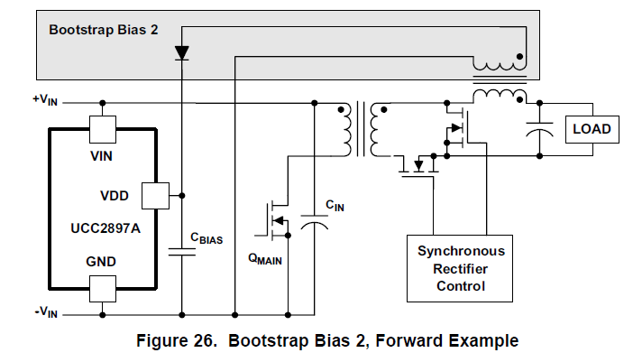
Our customer is using UCC2897A for 24V to 48V application, please see their schematic as below:

CED-BC01_0730_Power.pdf

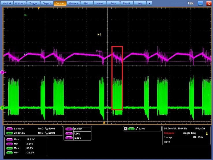
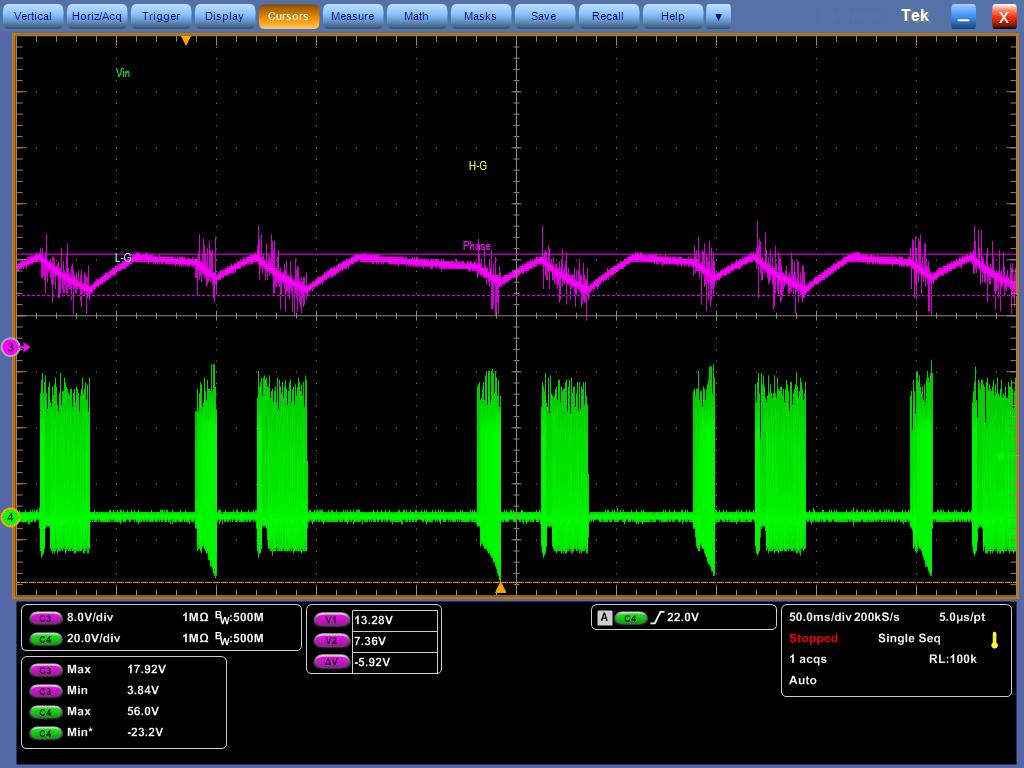
Currently. we got the power up fail issue and we figure out that PVDD power seems not stable enough and  lead to power up fail . please see the waveform of  PVDD vs Vout as below.

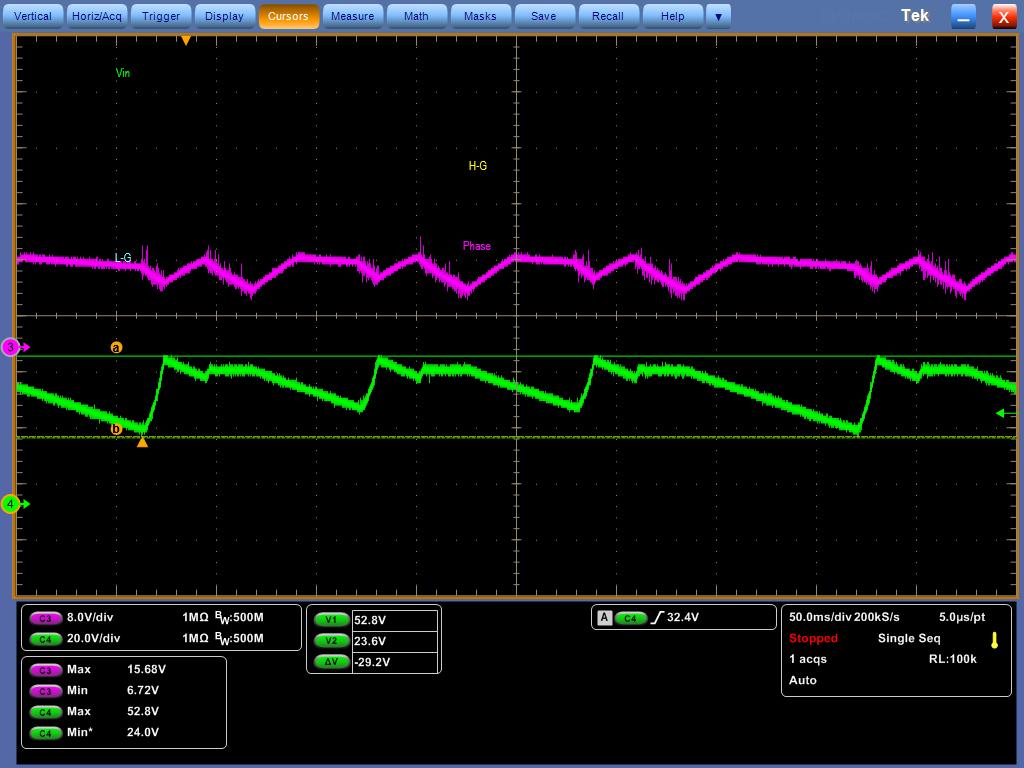
and here is the waveform for PL17 power input ans putout(measure both side if PL17, CH4 if the power in form transformer PT1 ) 

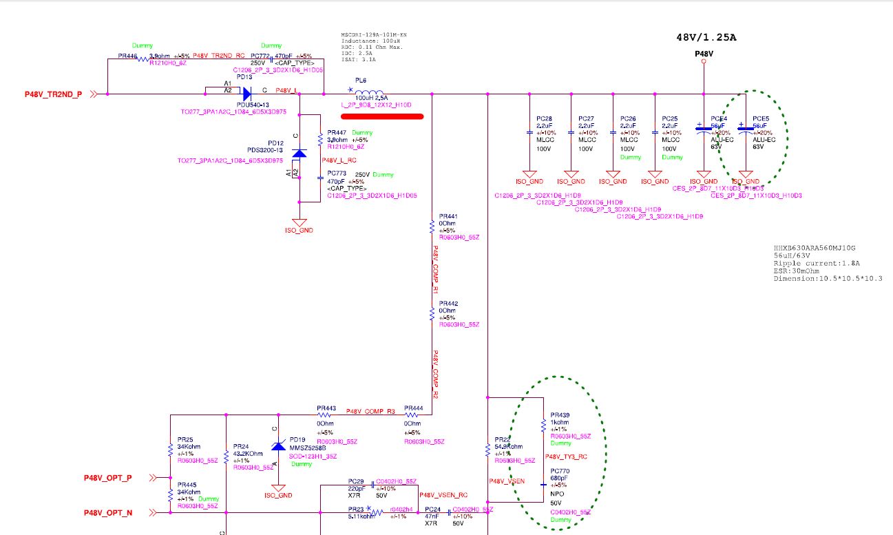
And we try disconnected the PL17(PVDD inductor)  and give PVDD an external 12V power rail, and then the Vout 48 V will be power up ok. Therefore, we have tried to adjust the inductor and capacitance value (the red circle as the schematic as below)

and it seems that we couldn't stable the PVDD voltage.Also, we have tried to add a small load on output and it seems help stable the PVDD( it seems like that small load help UCC2897A get out of pluse skipping mode), Could you kinldy help us check the application and  give us some advice for this issue? thanks in advance. also, we attach the transformer(PT1) and inductors(PL6, PL17) spec that they are currently use as your deference.

MSCDRI-129A-101M-EN_DS.pdf

MSCDRI-129A-101M-EN_DS.pdf

CEFD2513B(10393-T167)_RST-19-00465_1_Ext_20190611.pdf

Hope to heard form your soon.and if there is any question, please feel free to let me know

Alec

  • Hi Alec,

    In your schematic. the AUX winding  is unable to provide a quasi-regulated voltage for VDD and PVDD, since the "Dot end" of AUX winding is the same with Main winding. In a forward topology. the voltage across the AUX winding equals the input voltage times the turns-ratio of main winding and AUX winding. so the AUX voltage would vary with the input voltage . this configuration are not recommended in a forward-type topology.

    In the schematic, AUX winding , PD10, pd20,PL17 and PCE3 configured a BUCK converter to supply PVDD . but it's a open loop BUCK , the output voltage of this BUCK depends on the Duty cycle if input voltage and turns -ratio don't change.  At no load condition . UCC2897A entry skipping mode . in this mode , The duty cycle will change , lead to a variation PVDD . if you added some load on the output , you can get a more stable duty cycle . that is why you can got a more stable PVDD.

    We recommend below biasing circuit in a forward converter. since the output voltage is a regulated voltage.

    Hope can help you, Thanks.

  • Dear Sir,

    Thanks for the input and suggestion. Since customer's transformer is fixed and the PCBA is back. Therefore,  is there any solution that we could modify the currently schematic to make the application. please kindly let us know. 

    Cheers

    Alec 

  • Hi Sir, 

    We also look into the some of our customer 's design ,and  they seem all use the same application as the schematic that we provide in the previous mail and it seem work fine. and the only difference is that we use UCC2897A for 24V to 48V application and other customers are using on 48V to 12V or 5V. Could you kinldy also help us check with this?thanks in advance

    Cheers

    Alec


  • Hi Alec,

    In the schematic, PL17 is a 10nH value inductor . can you confirm it ? and you said you have tried some other value , could you tell me what kinds value had you tried ? obviously 10nH is a too small value which will lead to saturation of inductor . can you try 1mH ?

    Thanks.

  • Dear Sir,

    It is the schematic error, the actually inductor is 10mH. and we have tried 1mH, 470uF, the 47uF value with different capacitance and now it seems that 47uF+ 180 uF is the more stable now but the VDD voltage is only reach about 9~10V. please kinldy give us some advice about this. thanks a lot

    any other question, please feel free to let me know 

    Alec

  • Dear Sir,

    We are still co-work with RD. Currently still try to stable PVDD power input. At the meantime, we are wondering the waveform behavior shown as below. As you can see, CH 1 is PVDD(VDD), CH2 is OUT pin(Main MOS gate). In the red box of waveform. It looks that PVDD voltage drop when MOS gate is open.(phase is high). it looks kinds strange to us , could you kindly let us know why UCC2897A behave like that? any inputs are greatly appreciated  

    Above, if there is any question, please feel free to let me know

    Cheers

    Alec


  • Alec,

    As the controller starts switching it draws bias power from the CBIAS capacitor until the bootstrap winding takes over. During this time, VDD voltage is falling rapidly as the JFET is off but the bootstrap voltage is still not sufficient to power the control circuits. It is imperative to store enough energy in CBIAS to prevent the bias voltage from dipping below the turnoff threshold of the UVLO circuit during the startuptime interval. Otherwise the power supply goes through several cycles of retry attempts before steady-state operation is established.

    Please refer to the detail in section 8.3.2 on page 18&19 of the datasheet for more details.

    Best Regards

    Frank

  • Dear Frank

    We have co-worked with RD since the issue happened and it seems that we still can not stable the voltage on PVDD/VDD. Therefore, we suggest the customer to take your first advice by using the power design as below :


    Currently, the customer is considering it and at the meantime, they have let their transformer supply to provide the secondary transformer(the red circle one above) to match their design and here is the perlim spec:

    750344515r00 Prelim Spec Sheet.pdf  

    Could you kindly help us double confirming about the spec if it fit the design that you suggest at the beginning. thanks in advance

    Above, please kinldy help us checking the spec and hope to hear form you soon

    if there is any question, please feel free to let me know

    Cheers

    Alec

  • Hi  Alec,

    The maximum allowed voltage for VDD is 16.5V, if the output voltage is 48V, the recommended turns ratio is 4:1, rather than 2.46:1 in the datasheet.

    Thanks.

  • Dear Sir,

    We have discussed with RD about your suggestion, but we have a little question about your suggestion. in customer design, the main transformer is 1:5 and lt lead to 120 V on the secondary side(before inductor for the current design).So,  There would be 40% PWM duty to created 48V(please see the schematic as below). if we change PL6 into the 4:1 transformer , would it created 12V back to VDD/PVDD with 120V/duty 40% condition?Could you kinldy help us double check this? Also, RD is asking if TI have the tool to calculate the transformer ratio on UCC2897A design?? if yes, could you kinldy provide it to us? that would be a great help for customer to design UCC2897A in their project

    Above. if there is any question, please feel free to contact with me

    Cheers

    Alec

  • Hi Alec,

    Tha AUX winding in this configuration has not relationship with Main Transformer turns ratio and duty cycle . only with output voltage

    Output voltage is 48V , 12V is a suitable voltage for VDD/PVDD . that is why I proposed a 4:1 turns ratio.

    If the turns ratio is 2.46:1 , VDD voltage will reach to 19.5V , which already exceed the maximum allowed voltage for VDD.

  • Dear Sir,

    Thanks for the feedback, our customer have taken the advice and change the 4:1 ratio transformer , the spec looks ok to us and could you kinldy help double check the transformer spec as below? thanks in advance 

    2211.750344515r00 Prelim Spec Sheet.pdf

    Our customer are going into the next built very soon. Therefore, please kinldy feedback to us soon as you can.. 

    Alec

    Cheers

  • Hi,

    Sorry that i attach the previous transformer.  correct one as below. please kinldy help us check if the spec is suitable for their design. 

    2018.750344515r00 Prelim Spec Sheet.pdf

    Any question, please let me know

    Alec

  • Hi Alec,

    If you have additional questions, could you please create a new post and close this post. since there is a deadline on each post.

    We'll reply your questions on the new post.

    Thanks.