This thread has been locked.

If you have a related question, please click the "Ask a related question" button in the top right corner. The newly created question will be automatically linked to this question.

UCC28950: Need help to understand the IC functionality

Part Number: UCC28950

Hello all,

I am trying to make 1KW SMPS, I have done PFC circuit, Now from stepping down 400VDC to 28VDC I want to use PSFB converter as per webench suggestion.

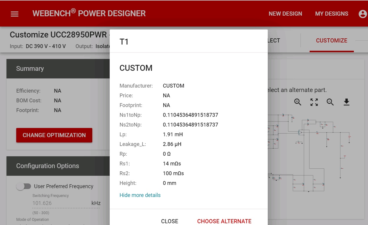
I have some queries on the design provided by the webench (attached .svg file to view the circuit from webench)

  • For isolation transformers from IC drivers. the turns ratio is given 1:1. Here, If the ratio is 1:1, then one secondary winding is having 400V, and another secondary winding is having ground. but the primary winding is getting 12V PWM. How can the PWM from primary side be transferred to the secondary side? I understand the windings are made in such a way that two windings can drive one half-bridge each. But unable to understand how the primary winding transformer will be able to drive the secondary coils with that much potential difference.
  • The transformer T1, with turns ratio of 0.110 i.e. Np/Ns = 390/40. I have asked a design for 390 down to 28VDC. but here both secondary windings are arriving at 40VDC with a centre tap of 20VDC. from 20VDC the LC filter is provided. How can the transformer designed for 40VDC be able to deliver 28VDC?

Please clarify me.WBDesign5.zip

Thanks,

Harika.

  • Hi Harika,

    The gate drive transformers are 1:1 turns ratio. The primary winding is driven the gate drive IC and I expect the Vcc for the gate drive IC to be in the region of 12V to 15V. This means the secondary side voltage of the gate drive transformer will also be in this range. One secondary of the gate drive transformer is driving the low side mosfet and is referred to 0V or ground. The other secondary which is physically isolated from the low side referenced secondary is tied to the switch node and this point moves between 0V when the low side fet is on and the PFC bus voltage when the high side fet is on. The secondary windings are two separate windings and the enamel insulation on the wire provides the insulation between the windings to allow them to operate with a potential difference between them. Pulse, Colicraft and Wurth-midcom have standard gate drive transformer available off the shelf.

    The transformer numbers do seem odd and I cannot access any information on the transformer design from the file that you sent me. Where did the 390/40 turns count come from ? The minimum input operating voltage will also impact the turns ratio.

    Can you take a screen shot of the transformer details from webench and post it?

    Thanks

    Peter

  • Hello Peter,

    Thanks for the reply, It did clear my doubts regarding the isolation transformer. 

    The transformer specifications are listed by webench tool itself (So based on 390*0.110 = 42V, I have arrived at conclusion that the transformer is giving 40V at each secondary winding with respect to the ground).

    Thanks,

    Harika

  • Hi Harika

    The peak winding voltage will be 40V but the operational duty cycle at 390V will be closer to 70% , 28V/40V. Which sounds about right.

    Regards

    Peter