This thread has been locked.

If you have a related question, please click the "Ask a related question" button in the top right corner. The newly created question will be automatically linked to this question.

UC2843: tempature rise in flyback topology

Part Number: UC2843

Hi all,

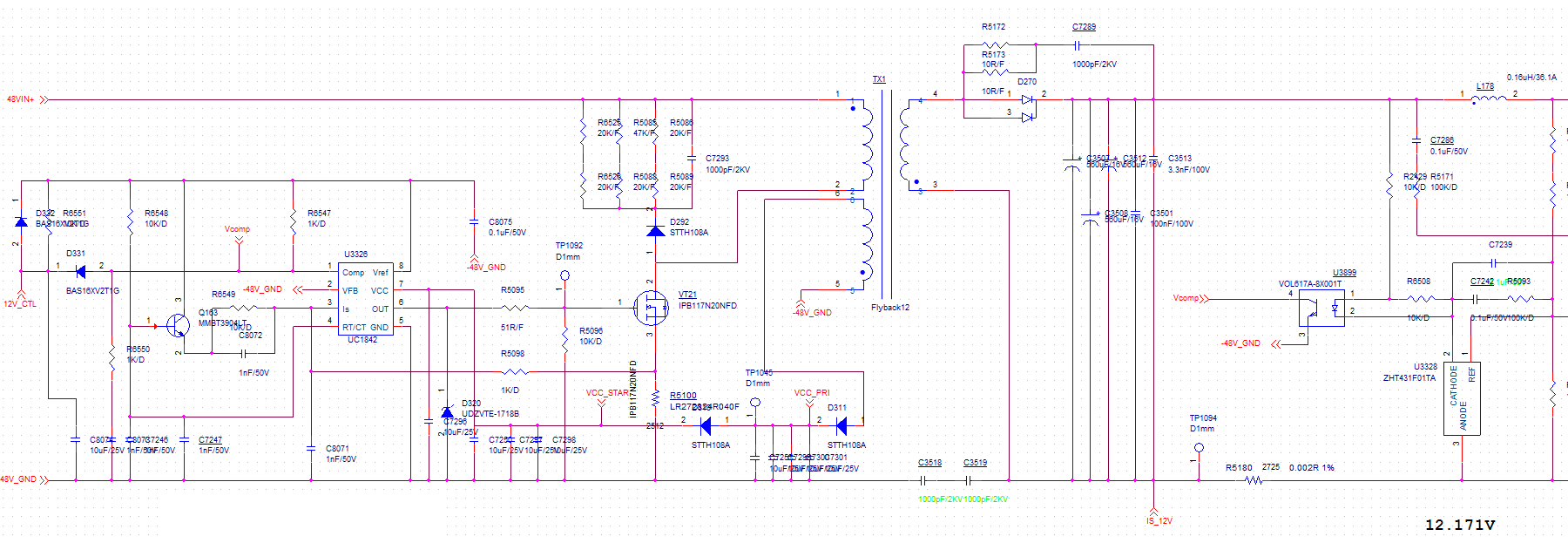
Customer use UC2843 in the control of flyback power supply.

Spec is: DC 48V input (37VDC~60VDC), output 12V/7A. Working environment: - 40 ~55 C. Because of the sealed environment, the temperature in the chamber may reach more than 70 degrees.

What is the power disspipation and tempature rise in this application?

  • Hi Jeff,

    The efficiency of power depends on many factors including transformer design, device selection and PCB layout.

    Considering mentioned power spec and operating condition, it is better to use a heat sink. 

    Regards,

    Teng

  • Hi Teng,

    I want to know the power dissipation of UC2843.

    According to datasheet, it will be VCC*supply sucrrent, is 25mA(IVCC) in datasheet should be used in this case? Thanks.

  • Hi Jeff,

    Total VCC current is the sum of quiescent VCC current and the average OUTPUT current. Quiescent VCC current is 0.5 mA. Knowing the operating frequency and the MOSFET gate charge (Qg), average OUTPUT current can be calculated as IOUTPUT = Qg × fSW.   Thus the power dissipation of device is PD = VCC * ( 0.5 + Qg × fSW).
    An estimation of the chip-junction temperature, TJ, can be obtained from the following equation:
    TJ = TA + ( RθJA × PD )...
    where: TA = ambient temperature for the package ( °C )
    RθJA = junction to ambient thermal resistance ( °C / W )
    PD = power dissipation in package (W)

    Regards,

    Teng