Dear Sir/Madam,
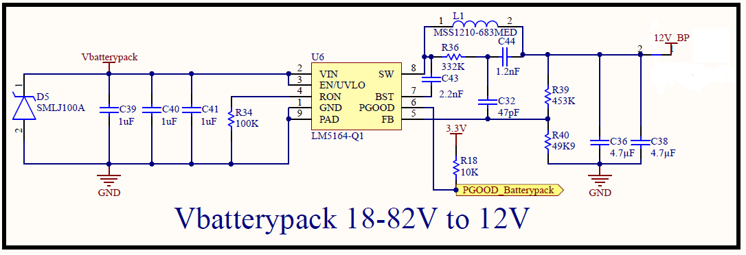
I used WEBENCH® POWER DESIGNER for the design of a buck converter.
The parameters I filled in are:
- Vin min: 15V
- Vin max: 100V
- Vout: 12V
- Iout Max: 1A
- IC: LM5164-Q1
When I tested the circuit it didn't give the right output.
The output was almost the same as the input and it is supposed to be 12V.
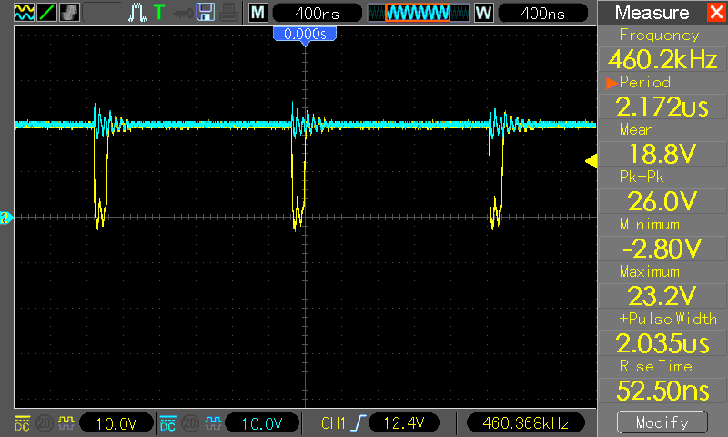
In the pictures are the measurements. (Blue is input voltage)
Output Voltage
Voltage before inductor
Feedback Voltage
I was looking at the datasheet and there was an application circuit with the same circuit only with different values.
In the application circuit was Rr the same as Rfbt so I changed Rr.
After that the circuit was working.
I don't understand why.
Could you explain it to me?
Or is the WEBENCH® POWER DESIGNER wrong and should I use the application circuit?
I would like to thank you in advance and I am looking forward to your reply.
Regards,
Roberto del Pozo Gallardo


