A related question is a question created from another question. When the related question is created, it will be automatically linked to the original question.
If you have a related question, please click the "Ask a related question" button in the top right corner. The newly created question will be automatically linked to this question.
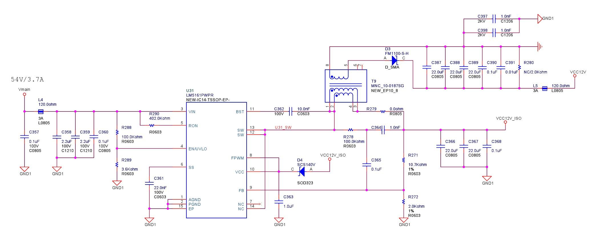
The schematic looks generally correct, although the 22uF/0805 caps may be low effective capacitance when 12V is applied.
I recommend using the LM5161 Fly-Buck quickstart calculator (download it from the product folder) to verify component values (particularly for ripple injection) This file is also useful to check current limit relative to the required load currents of the primary and secondary outputs.
Assuming you are using a 1:1 turns ratio "gapped" transformer with an Isat>1.9A and a leakage inductance<1% of Lprimary which should be around 120uH. Also make sure the RC values across the transformer is 300kohm and 3.3nF.